
Method for making a motor quieter

a motor and quiet technology, applied in the direction of single motor speed/torque control, electronic commutator, starter arrangement, etc., can solve the problems of motor weakening when operating at a low rpm, undesirable clicking noise in the stator winding of the coil, etc., to avoid clicking noise, unwanted clicking or snapping noise, the effect of avoiding noise problems

Inactive Publication Date: 2016-08-11
LD DESIGN ELECTRONICS
View PDF8 Cites 1 Cited by
  • Summary
  • Abstract
  • Description
  • Claims
  • Application Information

AI Technical Summary

Benefits of technology

The patent describes a method to make a motor quieter by using a special type of signal called a pulse width modulated signal. This signal is sent to two transistors that control the current in a stator winding. The first transistor conducts the current, but the second tranistor is switched to instead of the first transistor to induce transients in the stator winding. This is suppressed by a capacitor, which has to be a specific type of capacitor that can handle high voltages. The use of a zener diode helps to set a limit on the voltage of the capacitor. Overall, this method makes the motor quieter by reducing the noise caused by the current spikes.

Problems solved by technology

Nevertheless, brushless fan motors when operated, and when the stator energized electro-magnetic coils change polarization, an unwanted clicking or snapping noise can be heard particularly when the revolving fan blades do not override the clicking noise made by the fan motor.
When the rpm of the motor is only controlled by the variation of the voltage, the motor becomes weak when operating at a low rpm.
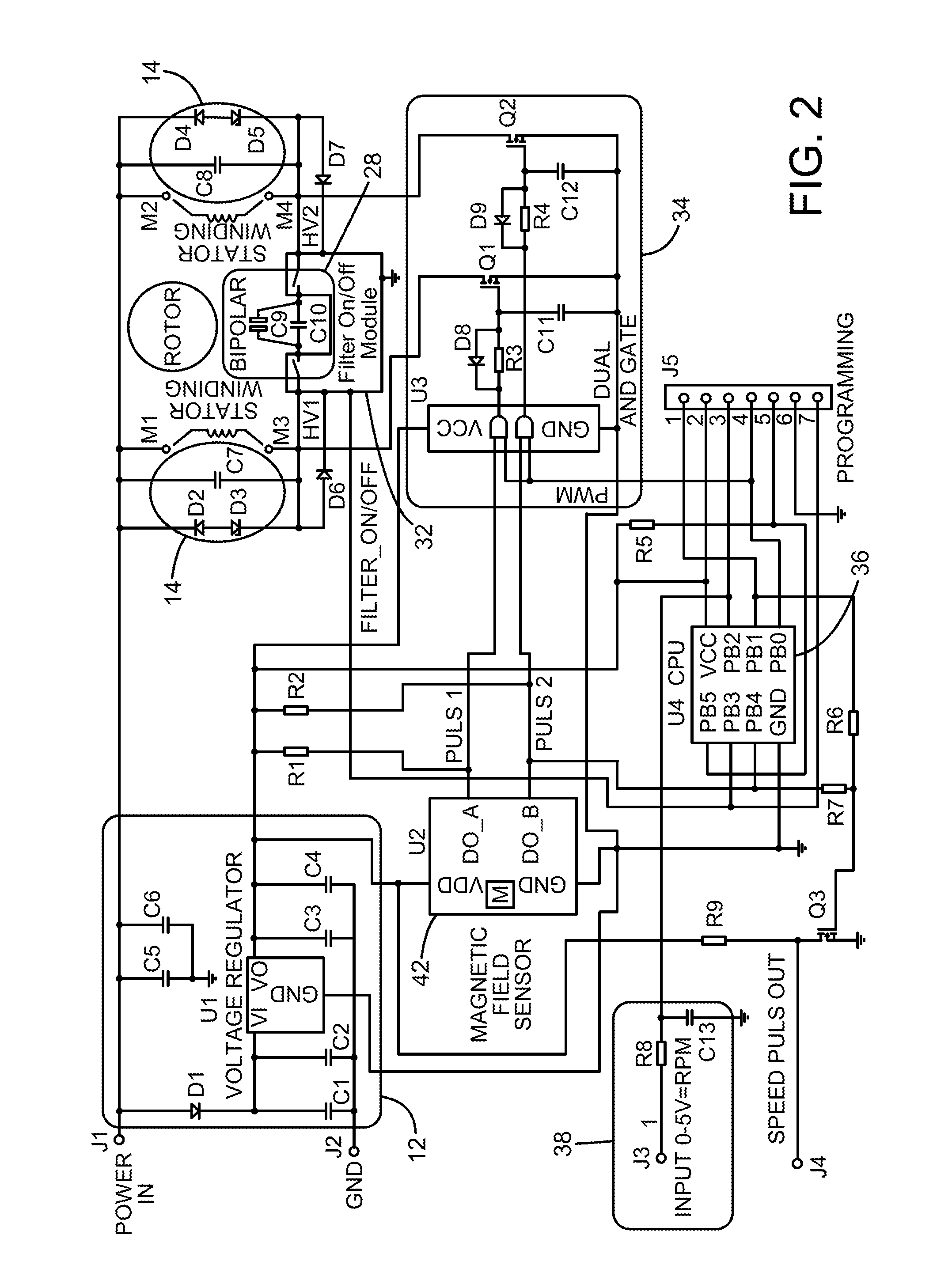
Rapid openings of the transistors, i.e. when the PWM pulses are not truncated, results in the sudden flow of current through the stator windings, which creates the undesirable clicking noise in the stator windings of the coils.
If only the coil inductance is used to limit the increase of the current, then the current rushes into the coils too fast and causes the undesirable clicking noise in the stator windings.
The sensor thus determines how fast the motor rotates but it does not necessarily determine at what rpm the motor should rotate.

Method used


Image

  • Method for making a motor quieter
  • Method for making a motor quieter
  • Method for making a motor quieter

Examples


Embodiment Construction

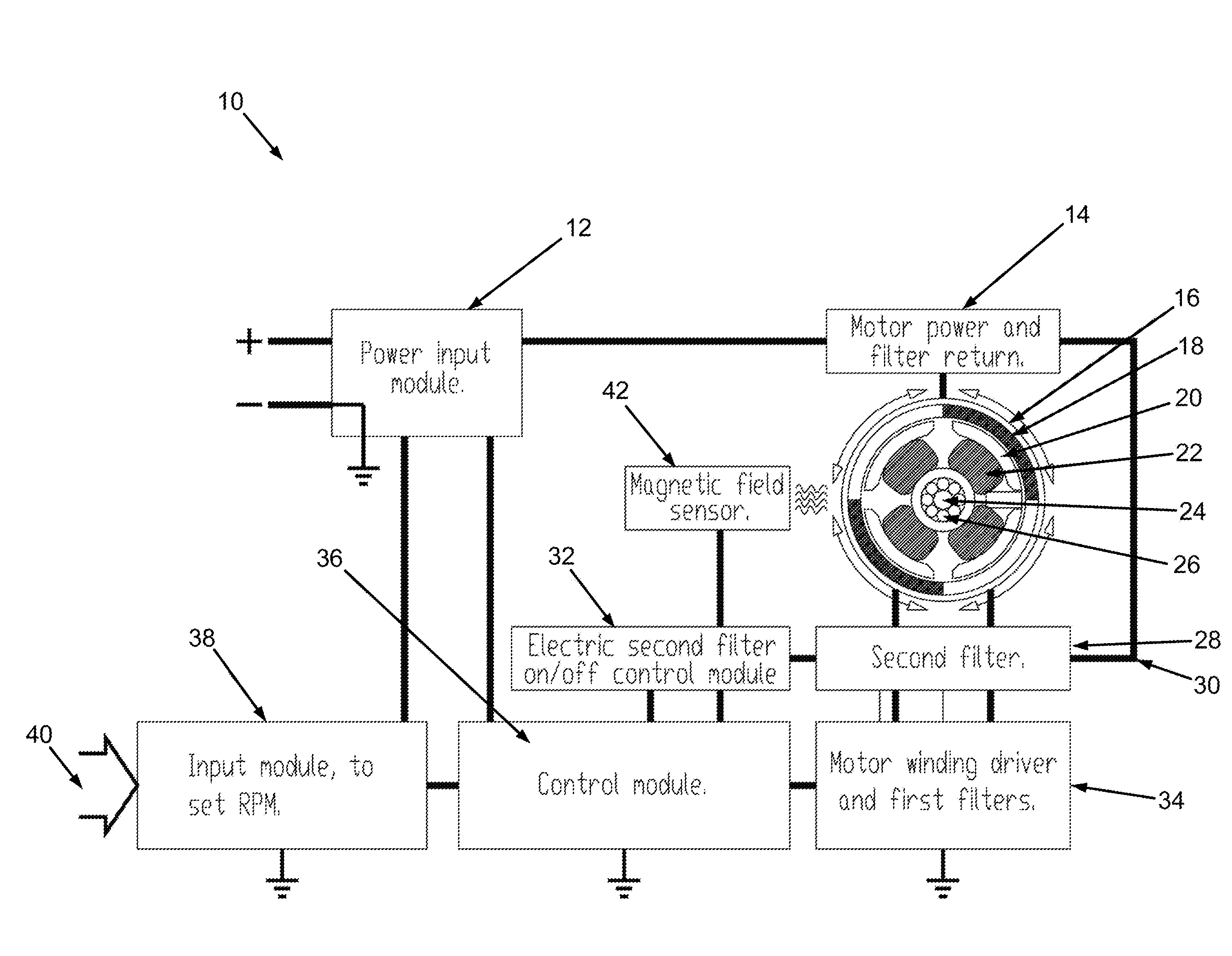
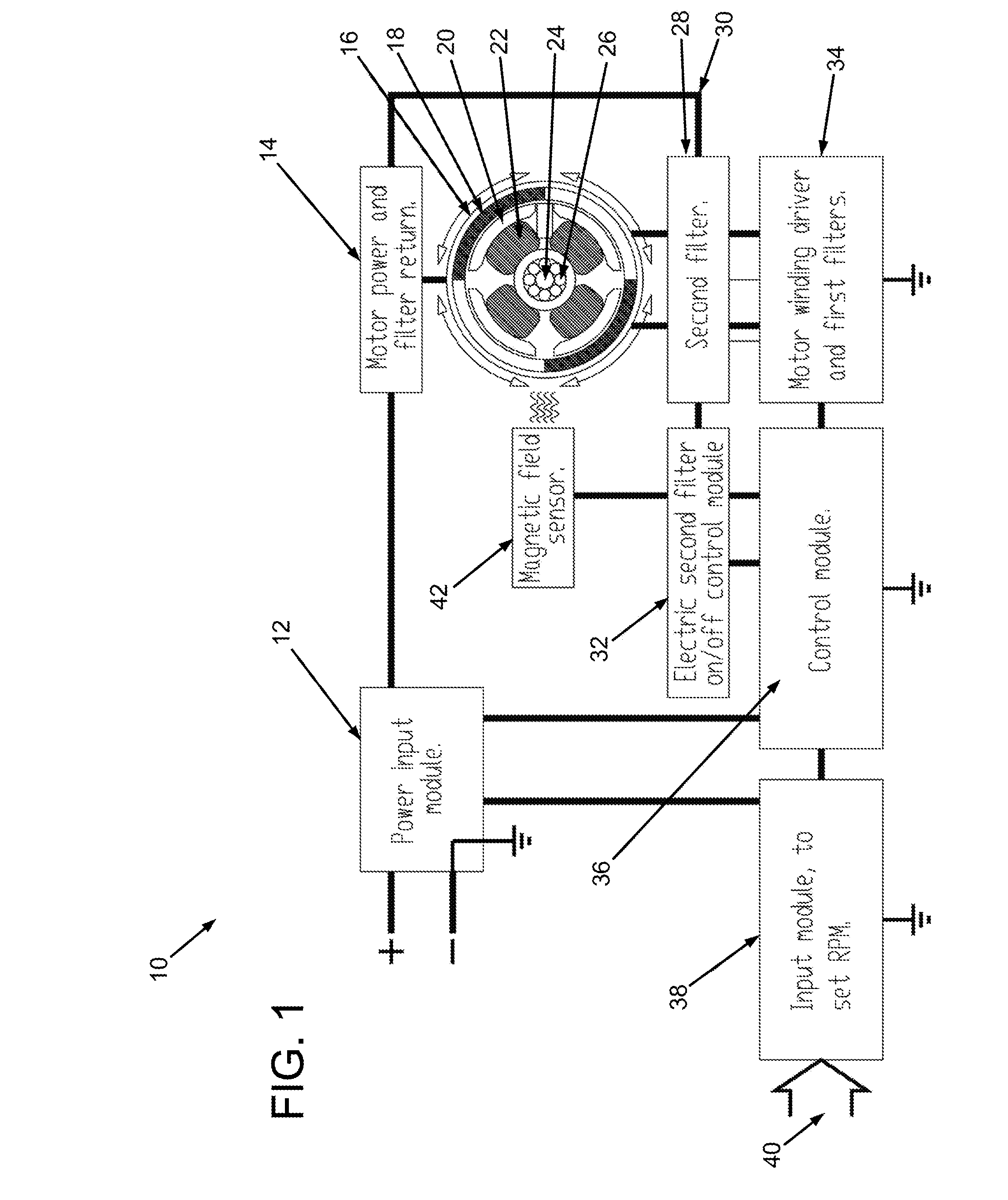
[0042]The present invention relates to a brushless DC motor made up of a stator with a number of windings which are magnetized by a current flowing through the different windings. It is to be understood that the invention is not limited to brushless DC motors and that any suitable type of motor may be used. The brushless DC motor is merely used as an illustrative example. The current at least partially depends on the windings number of turns, the area of the wire, and the applied PWM signal. Preferably, the stator windings should be wound so that the required power can be obtained with a high PWM frequency. Because the inductance opposes fast current changes, the windings should have a sufficiently low inductance so that desired current level can be reached. In other words, the stator should be wound in such a way that the desired or required current to achieve the desired rpm can be drawn through the windings can be accomplished at the PWM frequency used. If the inductance is too h...


PUM


Abstract

The method is for making an electric motor more efficient by iteratively changing when a processor sends activation signals to transistors to minimize a current required to rotate a rotor at a constant rotational speed. The method is also for changing a rotational direction of the rotor by switching the order in which activation signals are sent to the transistors.

Description

PRIOR APPLICATIONS[0001]This is a continuation-in-part application of U.S. patent application Ser. No. 13 / 974,089, filed 23 Aug. 2013.TECHNICAL FIELD[0002]The present invention pertains to a method for making a motor quieter such as a brushless direct current motor.BACKGROUND AND SUMMARY OF INVENTION[0003]Brushless fans are utilized in, for instance, computers, desktop fans, bathroom fans, and ventilation fans, and the like, because they are not as noisy as those operated by brushes. Nevertheless, brushless fan motors when operated, and when the stator energized electro-magnetic coils change polarization, an unwanted clicking or snapping noise can be heard particularly when the revolving fan blades do not override the clicking noise made by the fan motor. It is sometimes important that ventilation fans are as quiet as possible and the clicking noise should therefore be suppressed to avoid the noise problem.[0004]A brushless fan motor can be driven by direct current (DC) by feeding D...

Claims


Application Information

Patent Timeline
Patent Type & Authority Applications(United States)
IPC IPC(8): H02P6/15H02P6/22
CPCH02P6/153H02P6/08H02P6/22F04D27/004F04D29/663Y02B30/70
Inventor DERNEBO, LARS
Owner LD DESIGN ELECTRONICS
Learn More