
Semiconductor device

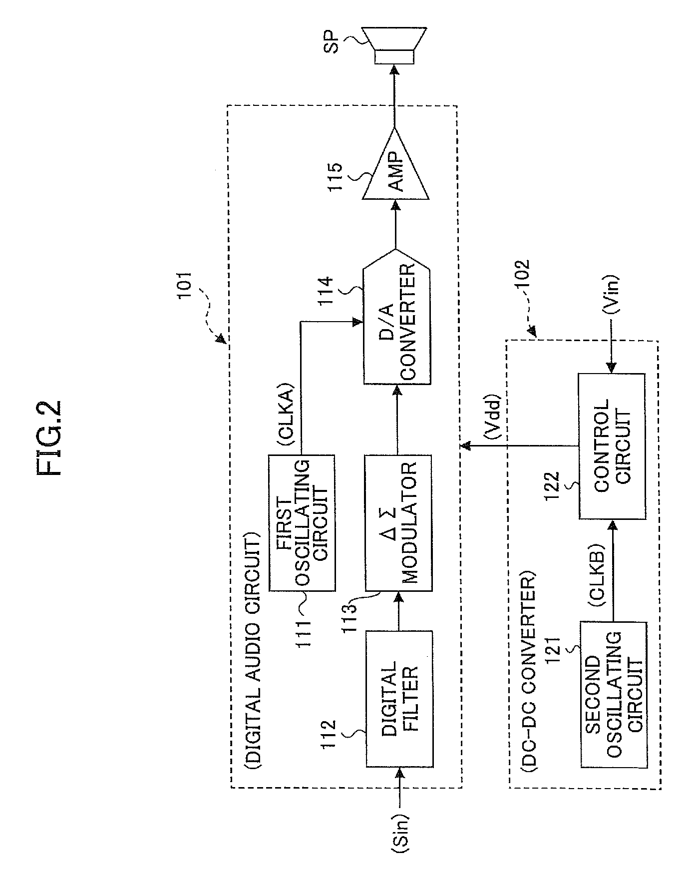
a technology of semiconductors and devices, applied in the direction of pulse generators, pulse techniques, electric pulse generator circuits, etc., can solve the problem of not considering the consideration of convertors

Inactive Publication Date: 2013-03-05
RICOH KK
View PDF21 Cites 0 Cited by
  • Summary
  • Abstract
  • Description
  • Claims
  • Application Information

AI Technical Summary

Benefits of technology

[0015]In an embodiment of the present invention, there is provided a semiconductor device which can remove a noise signal in the audible frequency range generated by a difference between a first clock signal in a digital audio circuit and a second clock signal in a DC-DC converter.
[0018]According to an embodiment of the present invention, a semiconductor device includes a digital audio circuit which converts an input digital signal into an analog audio signal, a DC-DC converter having a switching power source circuit, and an audible frequency determining circuit. In order that a difference between a frequency of a first clock signal for digital to analog conversion which is used in the digital audio circuit and a frequency of a second clock signal for switching control which is used in a DC-DC converter exceeds a maximum audible frequency, a frequency comparing circuit in the audible frequency determining circuit outputs a signal to a frequency changing circuit in the DC-DC converter. The frequency changing circuit causes a second oscillating circuit to change the second frequency. Therefore, unwanted noise in the audible frequency range in an audio signal can be prevented and clear sound quality can be obtained.

Problems solved by technology

In the conventional technology, the fluctuation of the output voltage from the power source circuit is corrected corresponding to the audio output; however, the frequency of a switching clock signal of the switching regulator serving as a DC-DC converter has not been considered.

Method used


Image

  • Semiconductor device
  • Semiconductor device
  • Semiconductor device

Examples


Embodiment Construction

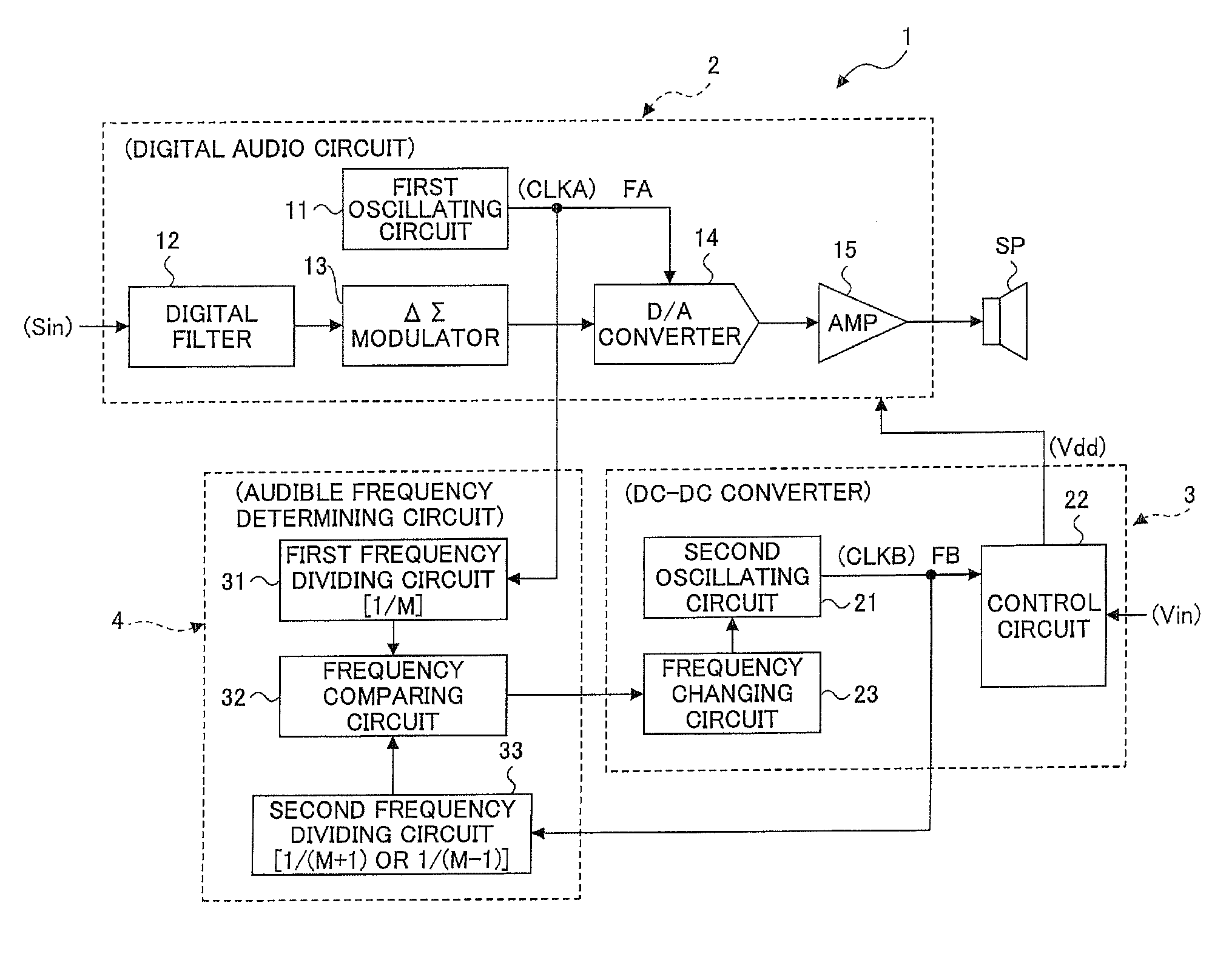
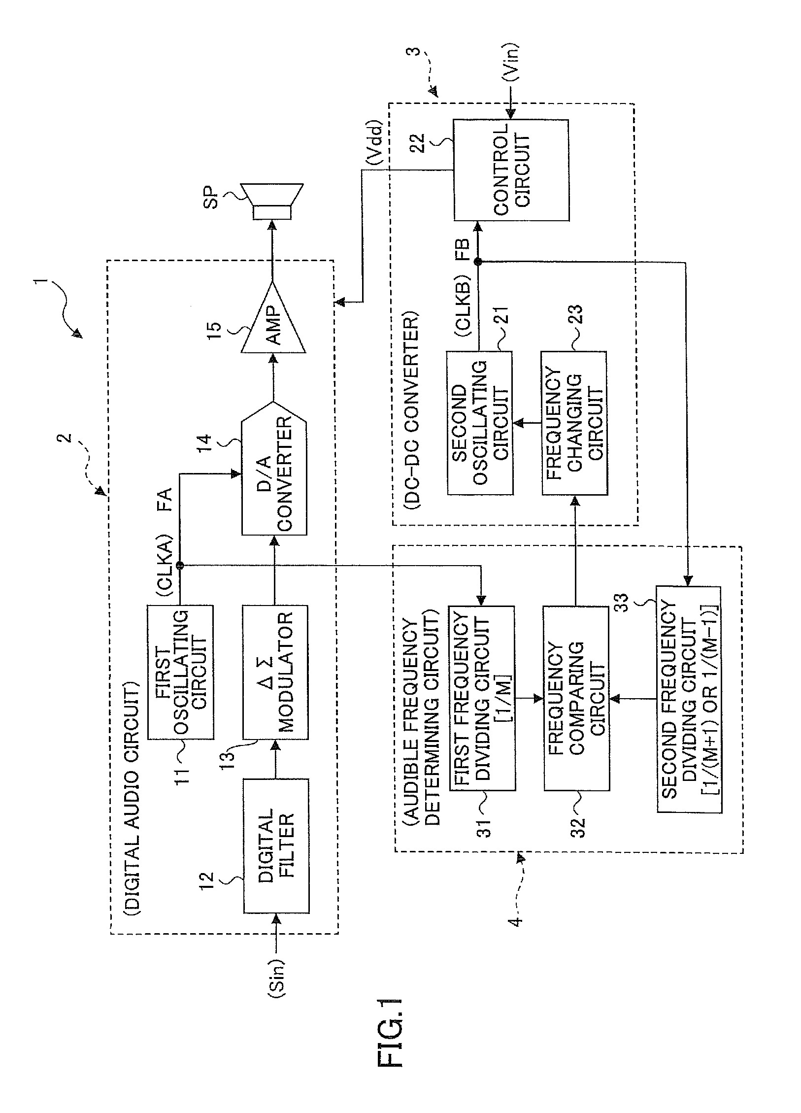
[0023]Referring to FIG. 1, an embodiment of the present invention is described in detail.

[0024]FIG. 1 is a block diagram showing a semiconductor device 1 according to the embodiment of the present invention.

[0025]As shown in FIG. 1, the semiconductor device 1 includes a digital audio circuit 2, a DC-DC converter 3 which is a switching power source circuit such as a switching regulator, an audible frequency determining circuit 4, and a speaker SP.

[0026]The digital audio circuit 2 includes a first oscillating circuit 11, a digital filter 12, a ΔΣ modulator 13, a D / A converter 14, and an output amplifier (AMP) 15. The DC-DC converter 3 includes a second oscillating circuit 21, a control circuit 22, and a frequency changing circuit 23. The audible frequency determining circuit 4 includes a first frequency dividing circuit 31, a frequency comparing circuit 32, and a second frequency dividing circuit 33.

[0027]A digital input signal Sin input to the digital audio circuit 2 is input to the ...


PUM


Abstract

A semiconductor device is disclosed. The semiconductor device includes a digital audio circuit which converts an input digital signal into an analog audio signal, a DC-DC converter having a switching power source circuit, and an audible frequency determining circuit. In order that a difference between a frequency of a first clock signal for digital to analog conversion which is used in the digital audio circuit and a frequency of a second clock signal for switching control which is used in a DC-DC converter exceeds a maximum audible frequency, a frequency comparing circuit in the audible frequency determining circuit outputs a signal to a frequency changing circuit in the DC-DC converter. The frequency changing circuit causes a second oscillating circuit to change the second frequency.

Description

TECHNICAL FIELD[0001]The present invention generally relates to a semiconductor device which includes a digital audio circuit and a DC-DC converter formed of, for example, a switching regulator for supplying a power source to the digital audio circuit.BACKGROUND ART[0002]As a conventional technology with respect to a digital audio circuit and a power source circuit for supplying a power source to the digital audio circuit, Patent Document 1 discloses an audio reproducing apparatus. The audio reproducing apparatus provides a control loop which detects a fluctuation of a power source voltage of a power amplifier and feed backs the fluctuation to a switching regulator; and another control loop which feed-forwards a signal generated from a PWM signal for controlling the power amplifier to the switching regulator. That is, the apparatus provides the feed-forward control, in addition to the feedback control. With this configuration, the fluctuation of the power source voltage can be accur...

Claims


Application Information

Patent Timeline
Patent Type & Authority Patents(United States)
IPC IPC(8): H03G5/00H04R3/00
CPCH03F1/0211H03F1/26
Inventor MICHIYOSHI, TAKSHI
Owner RICOH KK
Learn More