Media advancing device and method of displacing a medium

a technology of media advancing and advancing device, which is applied in the direction of electrographic process apparatus, instruments, printing, etc., can solve the problems of loss of pressure in the negative zone, and achieve the effect of reducing the gap, improving the containment of the zone, and precise manufacture of the shim

Active Publication Date: 2006-11-02
HEWLETT PACKARD DEV CO LP
View PDF15 Cites 1 Cited by
  • Summary
  • Abstract
  • Description
  • Claims
  • Application Information

AI Technical Summary

Benefits of technology

[0026] In this particular aspect, in order to control the size of the gap and to improve the containment of the zone of negative pressure, at least one shim obstructing said gap at least partially is provided. By a shim should be understood an additional mechanical piece having the function of reducing at least partially the gap between the platen and the overdrive roller. The advantages of having such a shim include the possibility of using a material different from the one used to manufacture the platen as well as a different manufacturing process allowing for example a more precise manufacture of the shim, thus allowing a reduction of the gap without consequence on the smooth rotation of the overdrive roller. In an embodiment, the platen comprises polycarbonate with glass fiber. In an embodiment, the overdrive roller comprises EPDM. In an embodiment, the shim comprises polycarbonate with fiber and PTFE.
[0027] It should be noted that the shim is placed against the bottom surface. This allows benefiting from a number of advantages. It should be understood that the design, dimensions, manufacture and fitting of a shim placed on the top surface is submitted to the constraints due to the displacement of the medium on the top surface. Such constraints disappear when the shim is placed against the bottom surface, thus providing a greater flexibility for the design, dimensioning, manufacture and fitting of the shim. The shim may for example be integrated to other mechanical pieces which should in any case be present below the bottom surface such as bearings for the overdrive roller, or may even be part of a housing for the part of the overdrive roller located below the top surface of the platen.
[0028] In an embodiment, a plurality of openings is provided. In another embodiment the top surface comprises a groove connected to the at least one of the openings. Such a groove is used to expand the area of suction of the medium. It should be noted that such grooves provided on the top surface should have a limited depth, which in an embodiment is of 1 mm, and merge substantially continuously with the top surface of the platen in the parts of the perimeter of the grooves which is not parallel do the direction of displacement of the medium in order to avoid trapping the medium into the groove. Indeed, the general direction of extension of such grooves follows in an embodiment the same direction as the direction of displacement of the medium. In another embodiment the top surface comprises a network of such grooves connected to the at least one of the openings. Such a network allows to further extend the area of influence of the opening, thus providing an improved repartition of the force for holding the medium down onto the top surface of the platen. In another embodiment, at least a part of the network of grooves surrounds at least partially the zone of the gap. Surrounding the zone of the gap with a part of the network of groove allows benefiting from the discontinuity introduced by the slot in the platen to further extend the active area. By active area, it is meant the area of the top surface in which a force is applied to the medium for holding it down on the platen. The active area is indeed best located directly around the overdrive roller, so that the medium is better held against the roller, thus increasing the friction between the roller and the medium, leading to a more efficient medium displacement.

Problems solved by technology

When only a part of the width of the platen is used, it may indeed be the case that an opening connecting the top surface of the platen to the zone of negative pressure is left uncovered by the medium, this resulting in a loss of pressure in the zone of negative pressure which would ideally have to be compensated adequately.

Method used


Image

  • Media advancing device and method of displacing a medium
  • Media advancing device and method of displacing a medium
  • Media advancing device and method of displacing a medium

Examples


Embodiment Construction

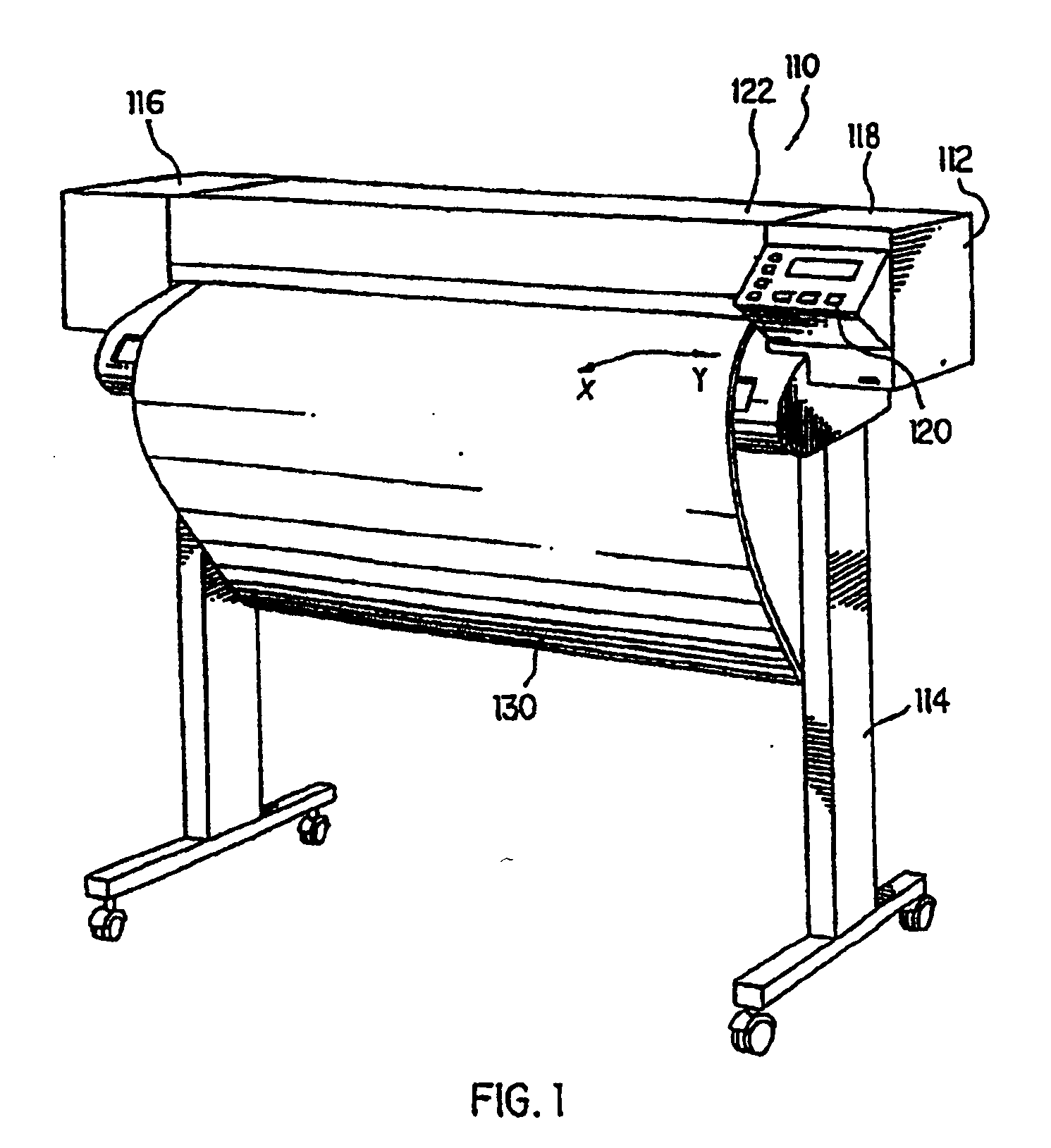
[0047] Referring to FIG. 1, a printer 110 includes a housing 112 mounted on a stand 114. The housing has left and right drive mechanism enclosures 116 and 118, and a cover 122. A control panel 120 is mounted on the right enclosure 118. A print media 130, such as media, is positioned along a media axis denoted as the X axis. A second axis, perpendicular to the X axis, is denoted as the Y axis.

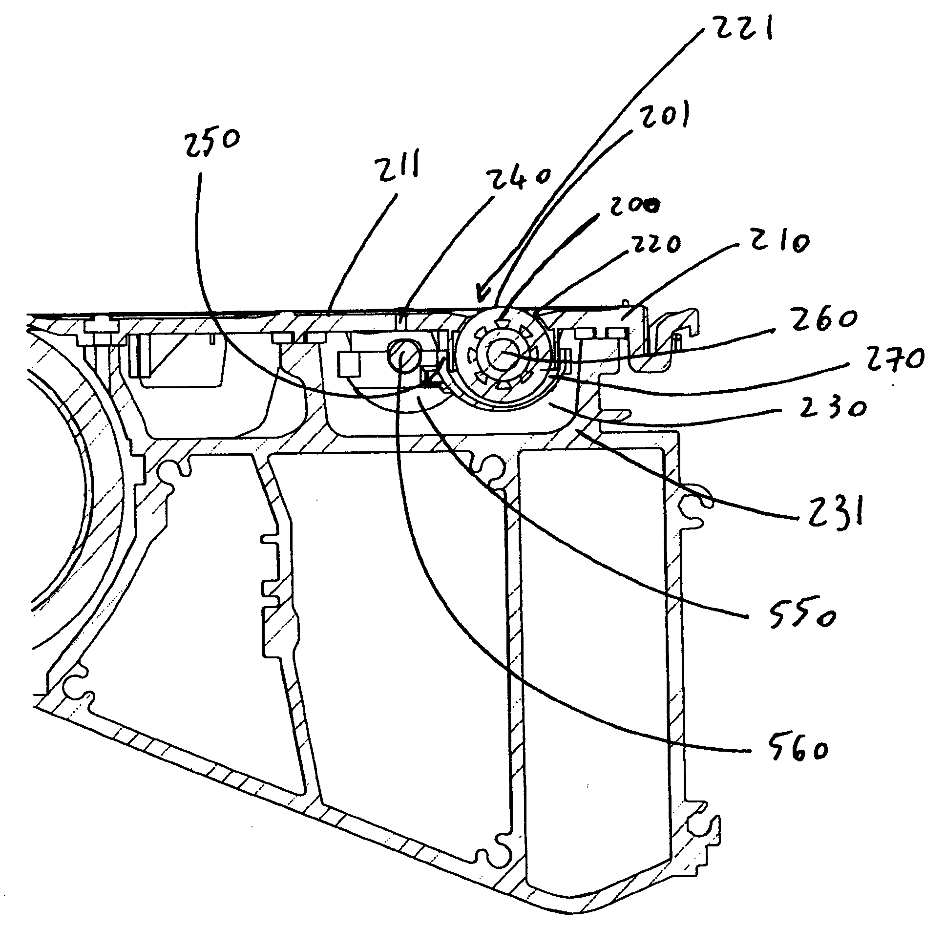
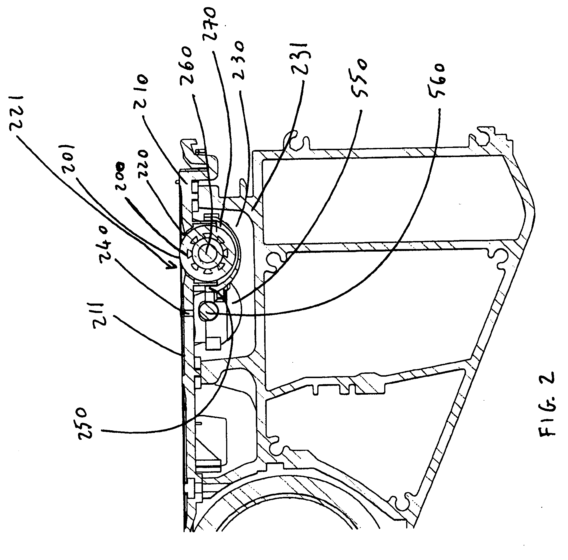
[0048] Referring to FIG. 2, a section view of an inkjet printer incorporating the features of the invention is represented where an overdrive roller 200 placed below a platen 210, the platen comprising a slot 221 through which the outer surface 201 of the roller emerges leaving a gap 220 between the outer surface and the slot. A vacuum chamber or zone of negative pressure 230 enclosed by a vacuum chamber cover 231 is placed below the platen and an opening 240 is provided into the platen to connect the top surface 211 of the platen to the vacuum chamber 230. The overdrive roller is placed in a h...


PUM


Abstract

A media advancing device for a hardcopy apparatus comprising: a platen having at least one slot and a top surface, whereby a medium advances on the top surface; and a plurality of openings connecting the top surface to at least one zone of negative pressure; and a revolving overdrive roller having an outer surface, the outer surface emerging above the top surface through the slot, the overdrive roller being substantially sealed in a housing below the top surface, the housing separating the overdrive roller from the zone of negative pressure.

Description

BACKGROUND OF THE INVENTION [0001] 1. Field of the Invention [0002] The present invention generally relates to hardcopy apparatus, such as copiers, printers, scanners, and facsimiles, and more particularly to improved media advancing devices for such apparatus. [0003] 2. Description of the Prior Art [0004] In hardcopy apparatuses and particularly in apparatuses handling media of large size, such as large format printers, a printed medium is outputted from the printer by outputting devices that may damage the quality of the printout. Conventional outputting devices, in order to advance printed media, employ elements for holding the medium having direct contact with the printed surface. This may cause markings on the medium, ink smearing and other adverse affects on the print appearance. [0005] As an example, the prior art has employed pinch wheels on top of the overdrive roller for outputting printed media. These devices may damage the printout with pinch wheel marks and further requ...

Claims


Application Information

Patent Timeline
Patent Type & Authority Applications(United States)
IPC IPC(8): B41J11/08B41J11/02
CPCB41J11/0085B41J13/03B41J11/06
Inventor TORAN, JOSE MIGUELGROS, XAVIERCASTELLS, RAIMON
Owner HEWLETT PACKARD DEV CO LP
Why Eureka
Try Eureka