[0009] The present invention has been made in view of the above circumstances and provides a push nut. According to one aspect of the invention, a push nut can be easily inserted onto a bolt, and the inserting work of the push nut can be done while the nut is pressed by two fingers, and the material yield of the push nut is high.
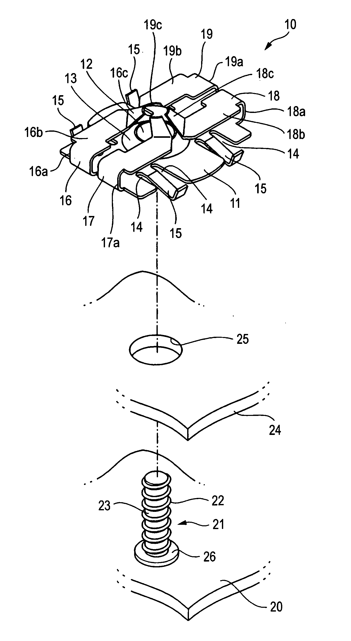
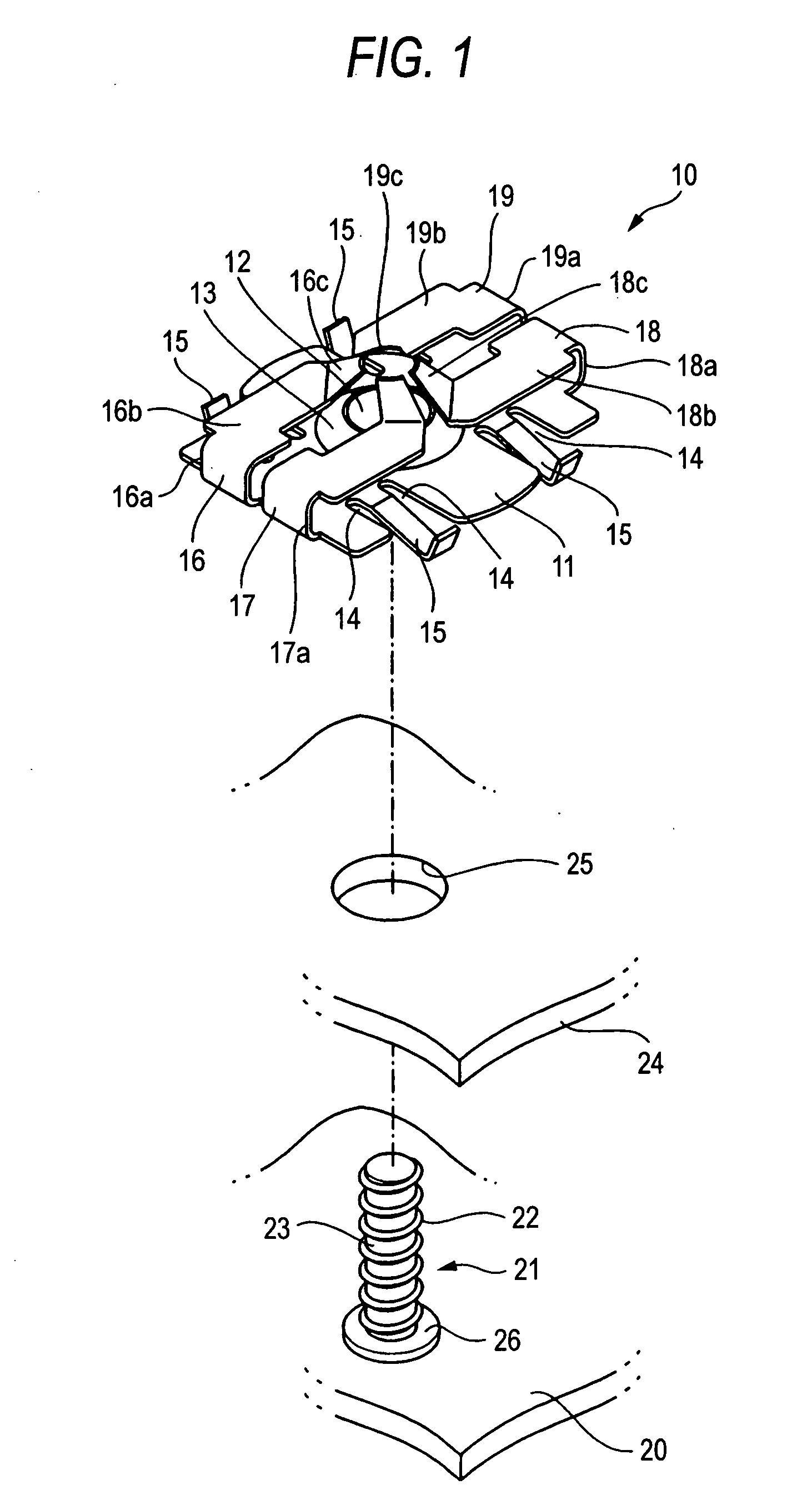
[0011] According to the above configuration, a tip end portion of the bolt is inserted into the bolt passing hole of the base plate from the
lower face side that is not in the direction along which the engaging pieces are folded back, and the push nut is pressed toward the base end of the bolt while the engaging pieces of the push nut are pressed by fingers. Then, the tip end portions of the four engaging pieces move toward a base end of the bolt while overriding the thread of the bolt, and, at positions where the base plate is in contact with an attached member, the tip end portions of the engaging pieces engage with a thread groove of the bolt to perform locking. In this case, a required locking force is ensured by the
coupling forces of the four engaging pieces. Therefore, the widths of the engaging pieces can be reduced, and the
insertion force to be applied on the bolt can be reduced to a relatively small degree. In the process of pushing onto the bolt, the push nut hardly inclines with respect to the bolt. Even when the push nut inclines with respect to the bolt, the case where
insertion is disabled does not occur. Therefore, the workability of attachment can be improved. Two of the engaging pieces extend from each of the pair of opposing sides of the base plate. Therefore, the push nut can be pushed by two fingers while two engaging pieces are simultaneously pressed by one of the fingers, and the push nut can be easily attached even in the case where the attachment work is conducted in a space where only the index and mid fingers can reach the engaging pieces. Since two of engaging pieces extend from each of the pair of opposing sides of the base plate, the shape in a developed state can be compact, and the material yield of the production process can be improved.
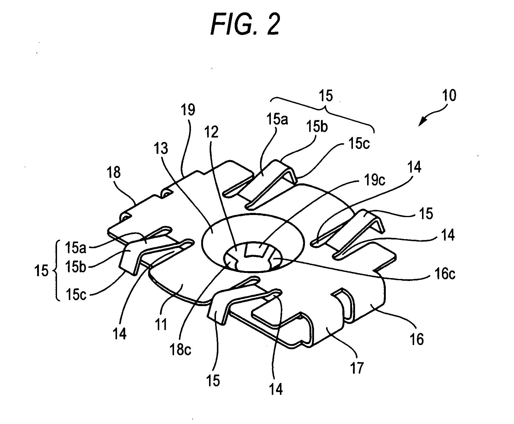
[0013] According to the above configuration, when pressed by fingers, the engaging piece of which the tip end portion is narrowed bends more flexibly, and moves more downward. As a result, when the engaging pieces are pushed maximumly, adjacent engaging pieces stop at different levels. By contrast, the thread groove in the outer circumference of the bolt is spiral, and hence the height of the thread is varied when the circumferential position is changed. When all the tip end portions of the engaging pieces are at the same level, therefore, the tip end portion of one of the engaging pieces overrides the thread. When adjacent engaging pieces stop at different levels as described above, however, each of the engaging pieces can engage with the thread groove, and rattling can be effectively prevented. The insertion resistances of the two engaging pieces are reduced, and therefore also the whole insertion resistance is reduced. Consequently, the insertion property can be improved.
[0015] According to the above configuration, the engaging piece in which the
angle of inclination of the tip end portion is small has a lower insertion resistance, and hence is pushed more inwardly. Therefore, adjacent engaging pieces stop at different levels. As a result, for the same reason as described above, each of the engaging pieces can engage with the thread groove, and rattling can be effectively prevented. The insertion resistances of the two engaging pieces are reduced, and therefore also the whole insertion resistance is reduced. Consequently, the insertion property can be improved.
[0017] According to the above configuration, in each of the engaging pieces, the length between a portion coupled to the base plate and the tip end portion can be increased as far as possible. Then the elastic force of the engaging piece can be enhanced. Therefore, the resistance of insertion onto the bolt can be reduced. Moreover, the base portions of two engaging pieces which extend from the same side of the base plate can be made close to each other, and hence it is easy to simultaneously press the two engaging pieces by one finger. Furthermore, the tip end portions of the four engaging pieces can be placed so as to evenly surround the periphery of the bolt passing hole. Therefore, the insertion resistance during insertion onto the bolt can be prevented from being biased, and the push nut can be prevented as far as possible from inclining in the process of being inserted.
[0018] As described above, according to a further aspect of the invention, the insertion force to be applied on the bolt can be reduced to a relatively small degree. On the way to push onto the bolt, the push nut hardly inclines with respect to the bolt. Even when the push nut inclines with respect to the bolt, the case where insertion is disabled does not occur. Therefore, the workability of attachment can be improved. Two of the engaging pieces extend from each of the pair of opposing sides of the base plate. Therefore, the push nut can be pushed by two fingers while two engaging pieces are simultaneously pressed by one of the fingers, and the push nut can be easily attached even in the case where the attachment work is conducted in a space where only the index and mid fingers can reach the engaging pieces. Since the shape in a developed state can be compact, the material yield of the production process can be improved.

