Automatic airplane seat location mapping

Active Publication Date: 2006-11-02
THE BOEING CO
View PDF10 Cites 38 Cited by
  • Summary
  • Abstract
  • Description
  • Claims
  • Application Information

AI Technical Summary

Benefits of technology

[0007] According to one aspect of the present invention, a ground wire is serially connected to a plurality of wireless clients or units in a wireless communication system. This single ground wire introduces much less cost and complexity into the system than would a serial or parallel data communication line. Each wireless client includes a switch that when closed provides a ground connection to subsequent clients. The ground connection is sequentially propagated al

Problems solved by technology

However, such techniques cannot be used with wireless systems, due i

Method used


Image

  • Automatic airplane seat location mapping
  • Automatic airplane seat location mapping
  • Automatic airplane seat location mapping

Examples


Embodiment Construction

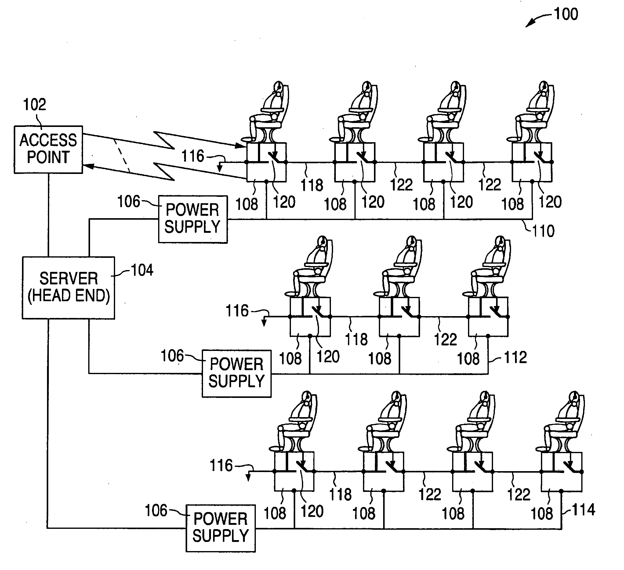
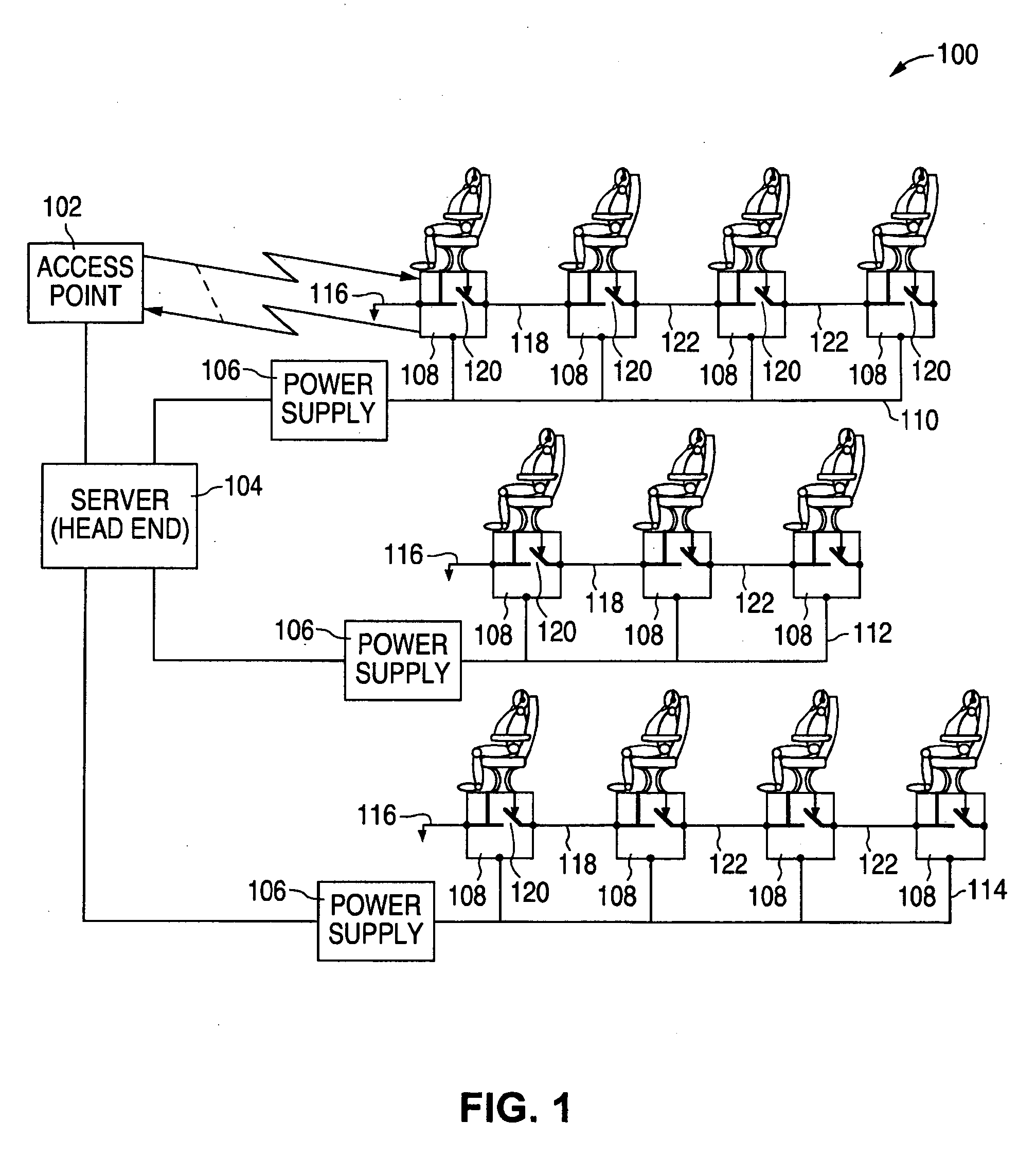
[0016]FIG. 1 is a diagram showing a system 100 for identifying and mapping units in a wireless communication system according to one embodiment. In this example, the wireless communication system is in an airplane, with the wireless units associated with seats on the airplane. System 100 includes a base station or access point (AP) 102, a server 104, such as an In-Flight Entertainment (IFE) Head End, three network controlled power supplies, such as 7E7 Remote Power Distribution Units (RPDUs) 106, and three columns of wireless stations or units 108. Each wireless unit is associated with an individual seat. System 100 is shown with four wireless units 108 in the first column, three wireless units 108 in the second column, and four wireless units 108 in the third column. The number of columns and wireless units shown in FIG. 1 is for illustration only, as any suitable number of columns and wireless units can be used with the present invention.

[0017] Each plurality of wireless units in...


PUM


Abstract

During a system reconfiguration, a selected column or column of wireless units, such as associated with airplane seats, are powered up. The first unit in the column detects a ground and begins a wireless identification process with an access point which allows the system to determine a corresponding physical location for each node's logical address. The first unit then closes a switch, which connects the ground to the next unit. As the next unit detects the ground on the line, such as a token line, the second unit communicates with the AP. This process continues sequentially down the column until the last unit is assigned a physical location/address. The next column of units can then be powered up and identified.

Description

BACKGROUND [0001] 1. Field of Invention [0002] This invention generally relates to identification of wireless users and, more particularly, to locating seats using wireless devices in an airplane. [0003] 2. Related Art [0004] In current airplanes, passengers can activate devices / indicators and communicate with the flight crew through various mechanisms, such as buttons or other controls located overhead, along the seat console, in front of the seat, or other convenient locations. With wireless communication technology becoming more accepted and widespread, communication between passengers in seats and airplane systems is being implemented using wireless technology, such as 802.11 protocols. However, in order to use wireless communication to activate seat-specific devices (such as reading lights and flight attendant call lights), the physical location of the seat unit needs to be known, in addition to any logical addressing assignments (such as IP address). For example, when a readin...

Claims


Application Information

Patent Timeline
IPC IPC(8): H04Q7/20H04W28/16
CPCH04W28/16
Inventor VONDOENHOFF, ROGER C.SHETTY, SUDHAKAR S.
Owner THE BOEING CO
Why Eureka
Try Eureka