
System for enlarging a retinal image

a retinal image and image technology, applied in the field of retinal image enlargement systems, can solve the problems of large visual acuity loss of affected people, difficult walking, and loss of the ability to read, and achieve the effect of enlarging the retinal imag

Inactive Publication Date: 2006-11-02
ESSILOR INT CIE GEN DOPTIQUE
View PDF16 Cites 27 Cited by
  • Summary
  • Abstract
  • Description
  • Claims
  • Application Information

AI Technical Summary

Benefits of technology

[0014] The invention provides a solution to one or more of these problems of the state of the art. It provides, in one embodiment, a system for enlarging a retinal image, comprising:

Problems solved by technology

This degeneration corresponds to a loss of the activity of the retinal rods situated in the macula and causes the affected person to lose a large part of his visual acuity.
In near vision, the affected person loses the capacity to read; in distance vision, walking becomes a difficult activity.
Currently no treatment exists that allows for this degeneration to be cured.
The system does not provide adequate vision in the absence of the lens with strong positive power.
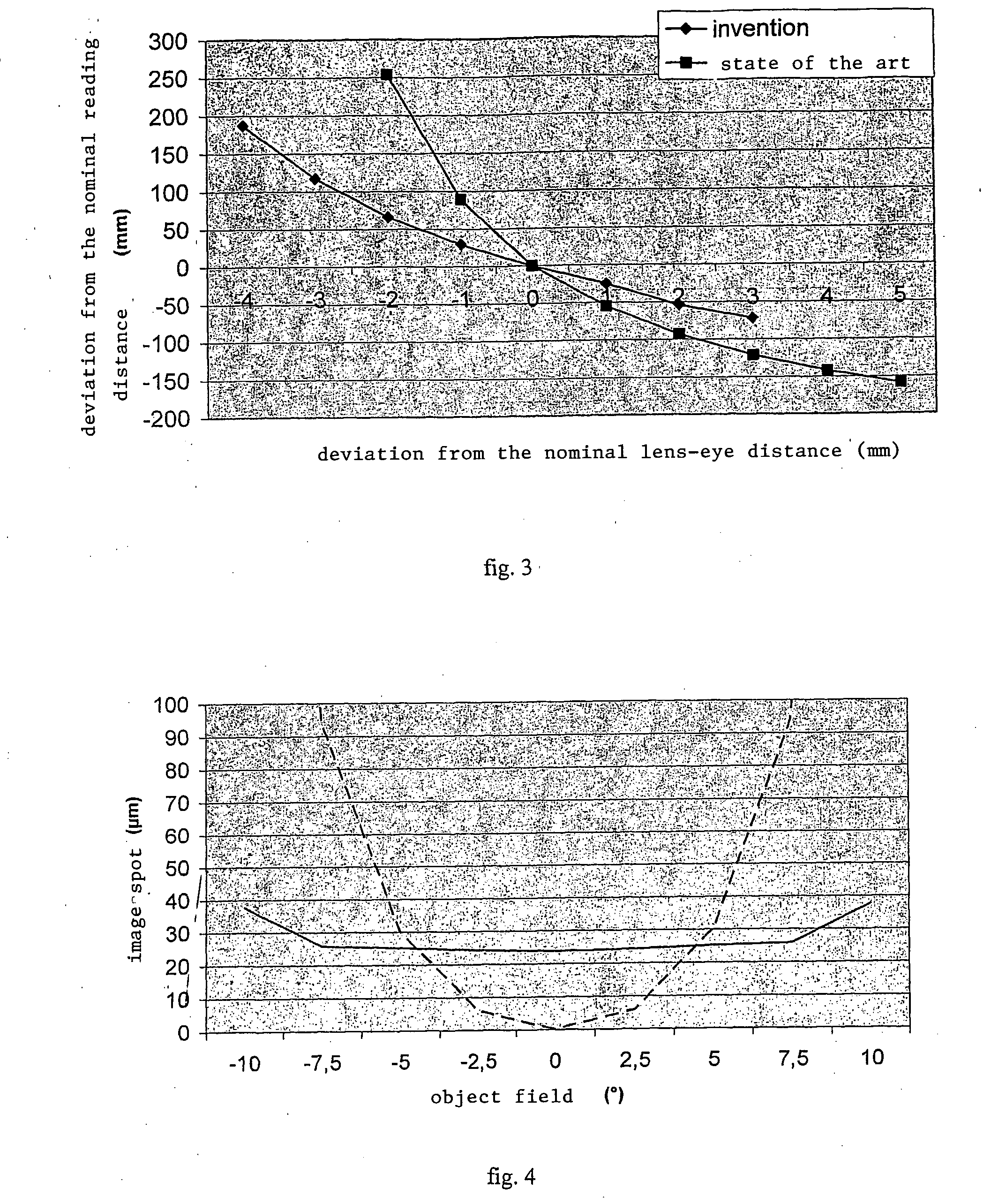
Another newly identified problem of the systems of the state of the art is that they are sensitive to incorrect positioning.
This is all the more problematic as the implantation cannot guarantee very precise positioning: regardless of the precision of implantation, the tissue grows after the operation and can lead to displacement of the implant.
Moreover, the system is designed for patients with visual impairment affected by macular degeneration; these patients have often lost their capacity to fix on an object, as a result of the loss of central vision, and generally use their peripheral vision without it being possible to guarantee that their eccentric direction of viewing is stable.
The age of the patient can also make it difficult to take measurements for precise positioning of the external lens.

Method used


Image

  • System for enlarging a retinal image
  • System for enlarging a retinal image
  • System for enlarging a retinal image

Examples


Embodiment Construction

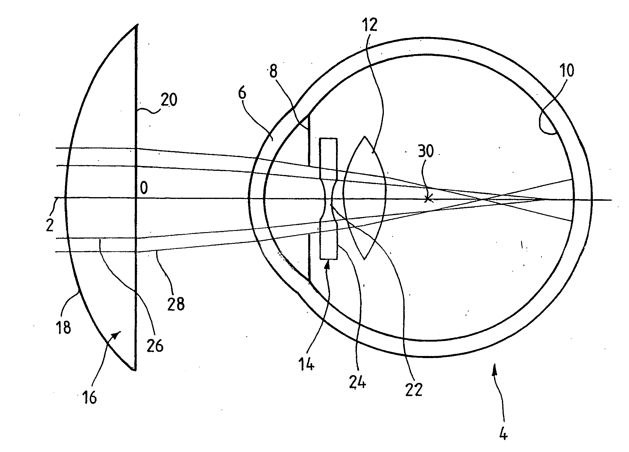
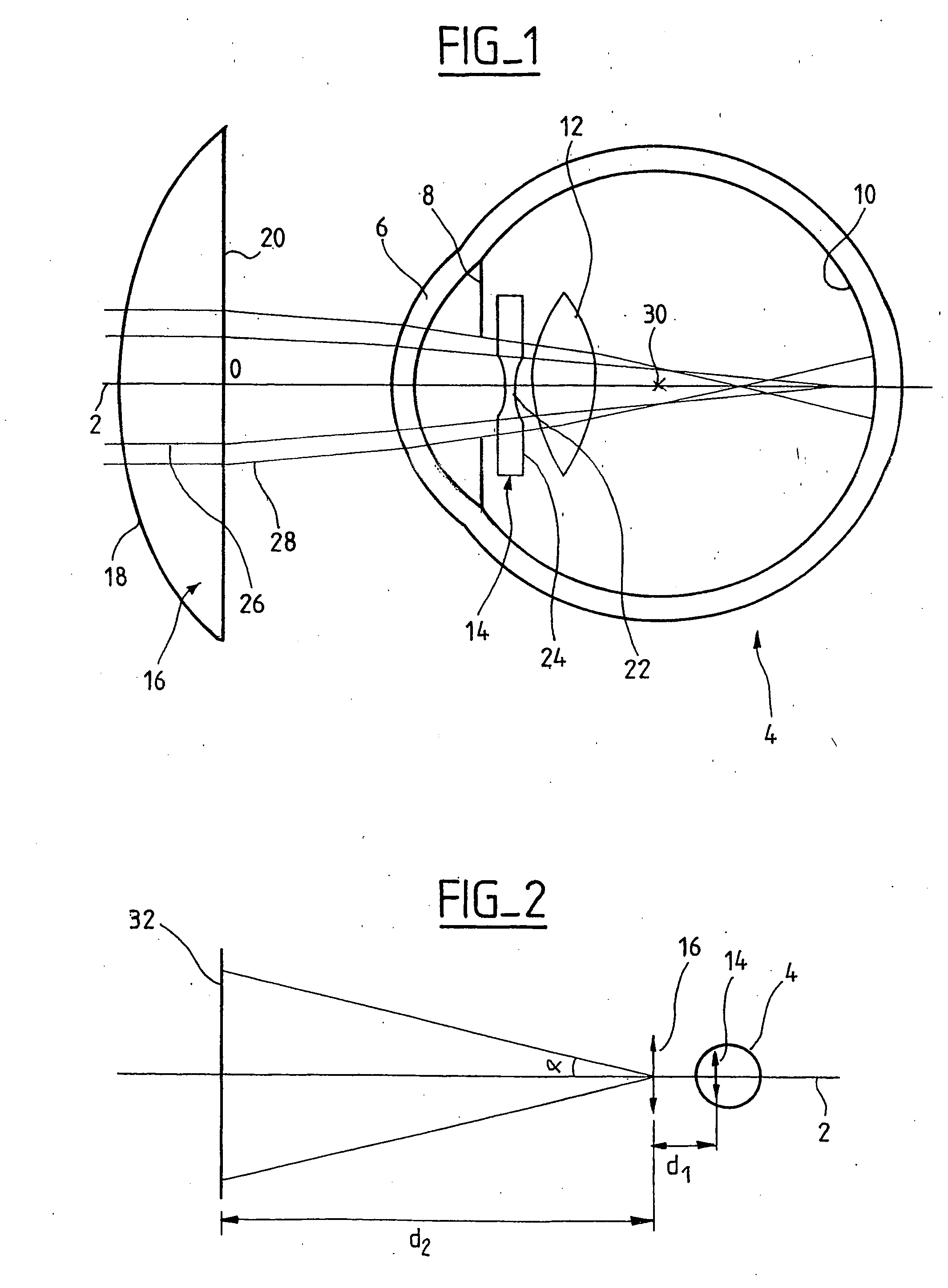
[0050]FIG. 1 shows a diagram of an eye-lens optical system according to the invention. The lens external to the eye is referred to in the following simply as a “lens”; likewise, the intraocular implant is designated simply by the term “implant” in the rest of the description. The lens and the implant produce a enlarging the image projected onto the back of the eye, in the manner of a telescope. The lens-implant assembly is therefore referred to in the following as a “telescopic system”, even though, strictly speaking, it is not a telescope.

[0051] In the figure an axis 2 corresponding to the primary direction of viewing is shown. The axis 2 passes through the center of rotation 30 of the eye 4. The eye is represented schematically; the cornea 6, the pupil 8, the retina 10, the crystalline lens or the intrasaccular implant 12 as well as an intraocular implant 14 according to the invention can be seen. The model proposed in Accommodation-dependent model of the human eye with aspherics...


PUM


Abstract

The invention relates to a system for enlarging a retinal image, comprising an intraocular implant and an external lens. The implant comprises a peripheral part and a central part with a negative power. The lens has a positive power and is for arrangement outside the eye, typically in a glasses frame. The lens and the implant produce an enlarged image of an object at the back of the eye of a standard user. For a pupil with a diameter of 1.5 mm, each point object in a reading field forms a dark image of a size between 20 and 50 μm at the back of the eye. The invention permits a large reading field, at the cost of a degradation in the performance of the system along the axis, acceptable when taking into account the acuity of the patients treated and, furthermore, provides a system with little variation in performance with displacement of the lens from the nominal position.

Description

CROSS REFERENCE TO RELATED APPLICATIONS [0001] This application is a continuation of, and claims the benefit of, international application number PCT / FR2004 / 002581, filed Oct. 12, 2004, which designates the United States and was published as PCT publication number WO 2005 / 037145, which in turn claims priority to French application number 0312009, filed Oct. 14, 2003. These applications are incorporated herein by reference.BACKGROUND OF THE INVENTION [0002] This invention relates to systems for enlarging a retinal image, used for optical correction of macular degeneration. [0003] Age-related macular degeneration (ARMD) is a disorder of the macula, which extends over the top of the retina at the back of the eye. This degeneration corresponds to a loss of the activity of the retinal rods situated in the macula and causes the affected person to lose a large part of his visual acuity. In near vision, the affected person loses the capacity to read; in distance vision, walking becomes a di...

Claims


Application Information

Patent Timeline
Patent Type & Authority Applications(United States)
IPC IPC(8): A61F2/16G02C7/02
CPCA61F2/1613G02C7/08A61F2/1648A61F2/1651
Inventor MARIN, GILDAS
Owner ESSILOR INT CIE GEN DOPTIQUE
Learn More