Supercharge Your Innovation With Domain-Expert AI Agents!

Method for updating software of an electronic control device by flash programming via a serial interface and corresponding automatic state machine

a technology of electronic control device and serial interface, which is applied in the direction of fault response, error detection/correction, instruments, etc., can solve the problems of long flash programming time in large flash memory of electronic control unit, inability to simultaneously export one program from a flash segment, and inability to exchange or remove control unit control units

Inactive Publication Date: 2006-11-02
ROBERT BOSCH GMBH
View PDF4 Cites 45 Cited by
  • Summary
  • Abstract
  • Description
  • Claims
  • Application Information

AI Technical Summary

Benefits of technology

[0010] During the signature check, a flash programming tool uses a further digital key to check whether the program stock or the data stock to be reprogrammed matches the control unit hardware and whether the program stock or data stock to be reprogrammed has been improperly manipulated after delivery by the vehicle manufacturer to the service organization, for example. Only after successful completion of the mentioned check should the actual deletion and programming of the respective segments of the flash memory be enabled or unblocked. Unblocking takes place here using the above-mentioned boot block. During specification of the security and reliability requirements for flash programming, it should be ensured that the signature of a microcontroller of the control unit is calculated subsequent to flash programming, on the basis of the program stock and data stock actually programmed into the flash memory in order to detect errors during programming. After a successful signature check, this calculated signature is stored in the flash memory. In addition, special memory structures, i.e., program stock and data stock logistics, are stored in the flash memory as part of the program stock and data stock. Only after a successful signature check, the boot block unblocks the activation of the new program, a drive program, for example.
[0011] Moreover, the availability requirement of the flash programming procedure is preferably specified in the method according to the present invention. Since flash programming via the off-board diagnostic interface may take up a relatively long period of time despite the above-described optimization measures, aborts of the programming procedure due to interferences may generally be anticipated at any time. Such interferences are, for example, failure of a voltage supply of a vehicle or of a flash programming tool, incorrect responses of other network control units, interruptions of the communication link between the electronic control unit and the flash programming tool used, or operating errors. Generally, failed authentication and failed signature checks also result in an abort of the flash programming procedure. Therefore, it may be important for a design of the flash programming procedure to ensure the availability of the flash programming procedure under all possible circumstances. This means, for example, that after an abort, a restart of the programming procedure should be ensured anytime in all situations. In a further preferred example embodiment of the method according to the present invention, substates, adoptable in the “software update” operating state, transitions between them, and transition conditions are specified by the finite-state machine during execution of the flash programming procedure. The substates may be the “abort/error message” substate or the “completion/success message” substate. Furthermore, substates for authentication and signature check as well as substates for the deletion and programming

Problems solved by technology

A software update is thus possible without removing the respective electronic control unit from the vehicle, which results in considerable cost savings compared to a control unit exchange or removal.
Moreover, it should be taken into consideration that it is not possible to simultaneously export one program from a flash segment while another flash segment of the same flash module is reprogrammed.
The limited transmission capacity of the off-board diagnostic interface results in quite long flash programming times in large flash memories of electronic control units.
Finally, it should be pointed out that flash programming via the mentioned off-board diagnostic interface may take up a relatively long period of time.
Such interferences are, for example, failure of the voltage supply of a vehicle or of the flash programming tool, incorrect response of other network control units, interruption of the communication link between the electronic control unit to be programmed and the flash programming tool used for this purpose, or an operating error.
A failed authentication and signature check may also result in the abort of the flash programming procedure.
The limited transmission capacity of the off-board diagnostic interface results in quite long flash programming times in large flash memories.
Since flash programming via the off-board diagnostic interface may take up a relatively long period of time despite the above-described optimization measures, aborts of the programming procedure due to interferences may generally be anticipated at any time.
Such interferences are, for example, failure of a voltage supply of a vehicle or of a flash programming tool, incorrect responses of other network control units, interruptions of the communication link between the electronic control unit and the flash programming tool used, or operating errors.
Generally, failed authentication and failed signature checks also result in an abort of the flash programming procedure.

Method used


Image

  • Method for updating software of an electronic control device by flash programming via a serial interface and corresponding automatic state machine
  • Method for updating software of an electronic control device by flash programming via a serial interface and corresponding automatic state machine
  • Method for updating software of an electronic control device by flash programming via a serial interface and corresponding automatic state machine

Examples


Embodiment Construction

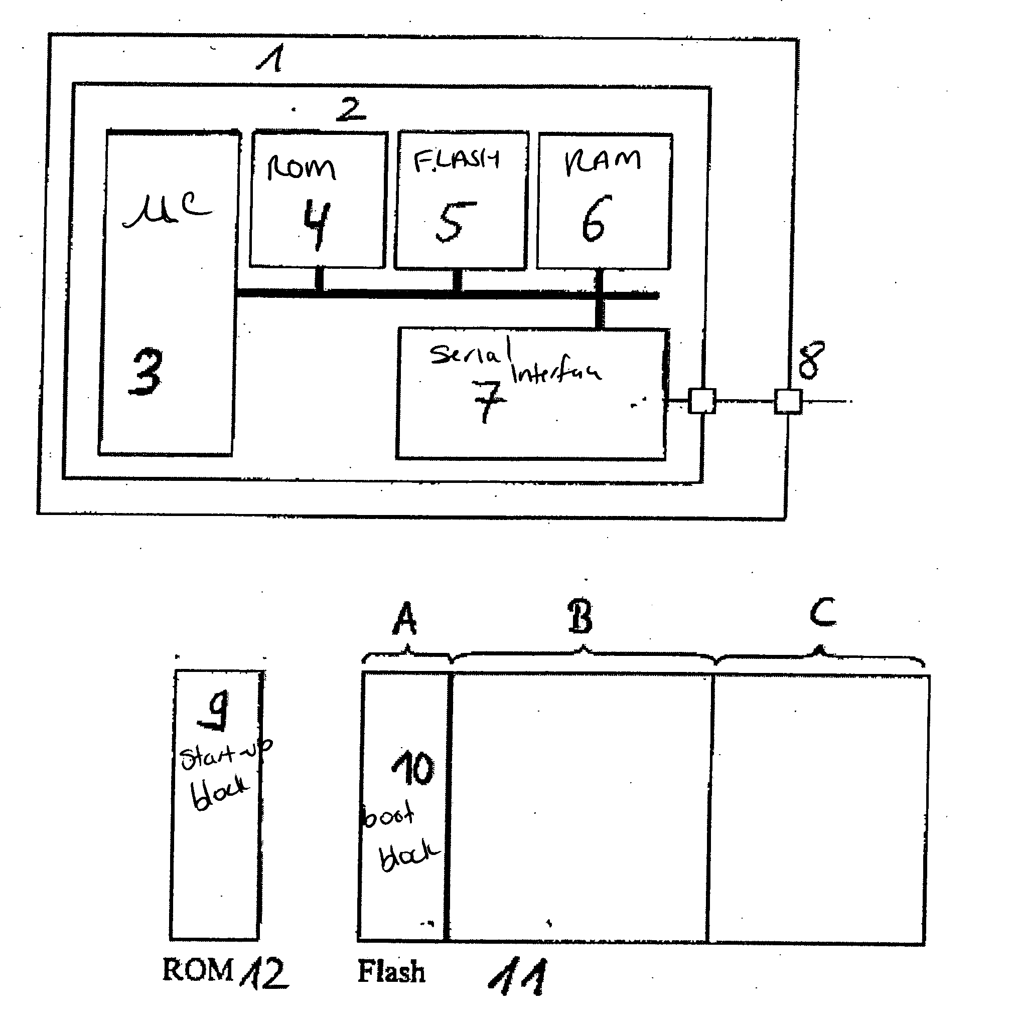
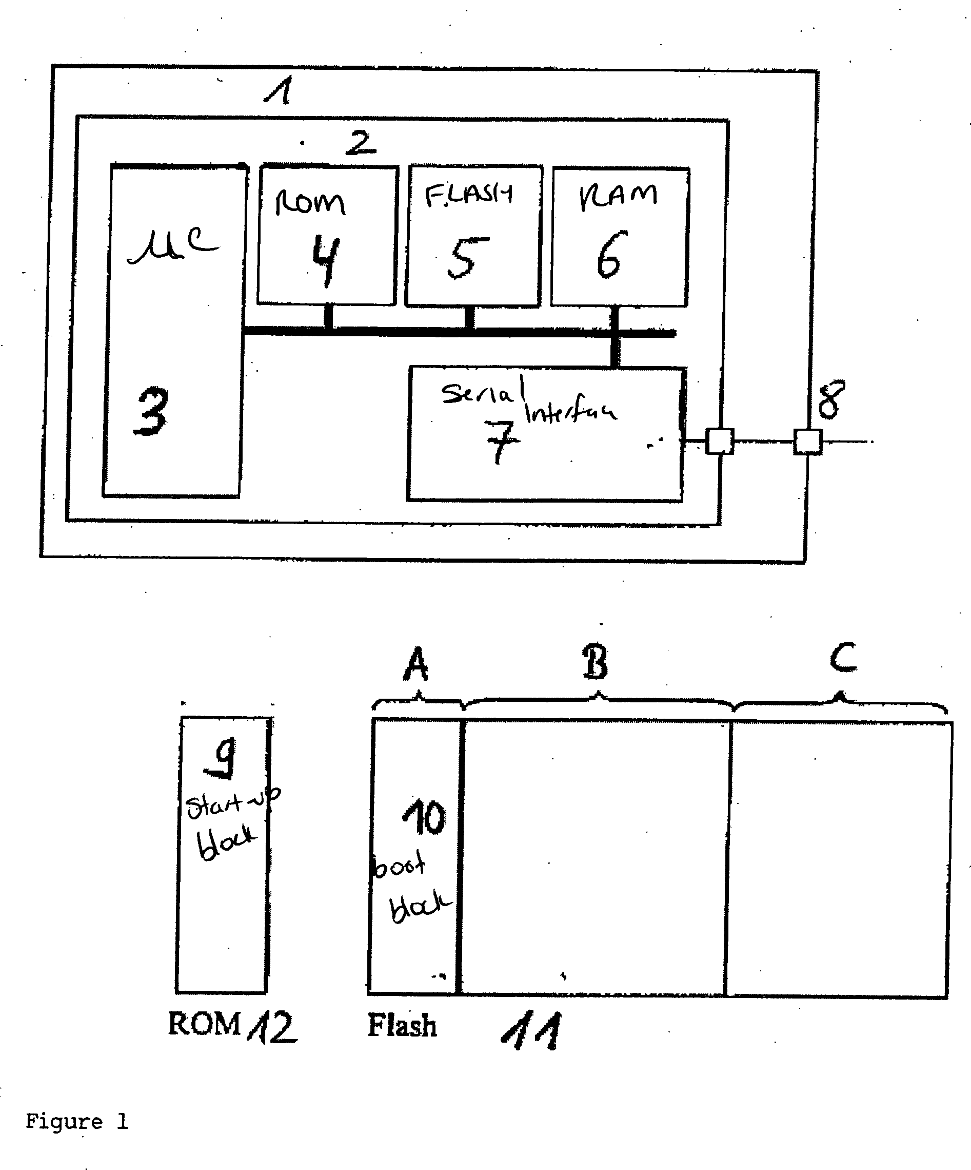
[0019]FIG. 1 shows an allocation of memory arrays of a software of a control unit for executing a software update of a control unit by flash programming. A control unit 1 having a microcontroller 2 is shown. Microcontroller 2 has a microprocessor 3 and three different memories, namely a ROM (read only memory) 4, a flash memory 5, and a RAM (random access memory) 6. In addition, control unit 1 has a serial interface 7 for coupling to an off-board diagnostic interface 8 via which a flash programming tool may be connected. A memory allocation of memory arrays of the software of control unit 1, relevant for the flash programming procedure, is shown in the lower part of FIG. 1. The memory arrays are divided into programmable and non-programmable memory arrays and software components to be reprogrammed are correspondingly assigned to the memory arrays. Program sections of microcontroller 2, which are used for communication between microcontroller 2 and a flash programming tool via off-boa...


PUM


Abstract

A method for executing a software update of a control unit by flash programming a flash memory of the control unit having multiple segments via a serial interface, demands on the flash programming procedure being established, a sequence of the flash programming procedure being specified by a finite-state machine which defines states and transitions of the software, and availability, security, and reliability requirements of each state and each transition of the finite-state machine being checked. In addition, described are a corresponding finite-state machine and a computer program for automatically checking the availability, security, and reliability requirements.

Description

FIELD OF THE INVENTION [0001] The present invention relates to a method for executing a software update of an electronic control unit using flash programming via a serial interface. BACKGROUND INFORMATION [0002] Flash memory is increasingly used as memory technology for program stock and data stock in electronic control units. This memory technology makes a software update of the control units possible by reprogramming the respective flash memory of the control units via serial interfaces. The serial interface may be, for example, a central off-board diagnostic interface of a vehicle via which the flash memory of an electronic control unit of the vehicle is reprogrammed using what is known as a flash programming tool. A software update is thus possible without removing the respective electronic control unit from the vehicle, which results in considerable cost savings compared to a control unit exchange or removal. In the described type of flash programming, high security and reliabi...

Claims


Application Information

Patent Timeline
IPC IPC(8): G06F15/177G06F9/445G06F11/14G06F21/57G11C
CPCG06F8/665G06F21/572G06F11/1433G06F8/654
Inventor ZURAWKA, THOMASSCHAEUFFELE, JOERG
Owner ROBERT BOSCH GMBH
Features
  • R&D
  • Intellectual Property
  • Life Sciences
  • Materials
  • Tech Scout
  • Unparalleled Data Quality
  • Higher Quality Content
  • 60% Fewer Hallucinations
Learn More