[0007] One or more embodiments of the present invention provide an apparatus and a method for folding and forming a prepreg, in which it is prevented from increasing a running cost caused by the prolonged
heating time and the prolonged folding and forming time and stabilized quality of the prepreg is obtained, even if a thickness of the laminated prepreg is large.
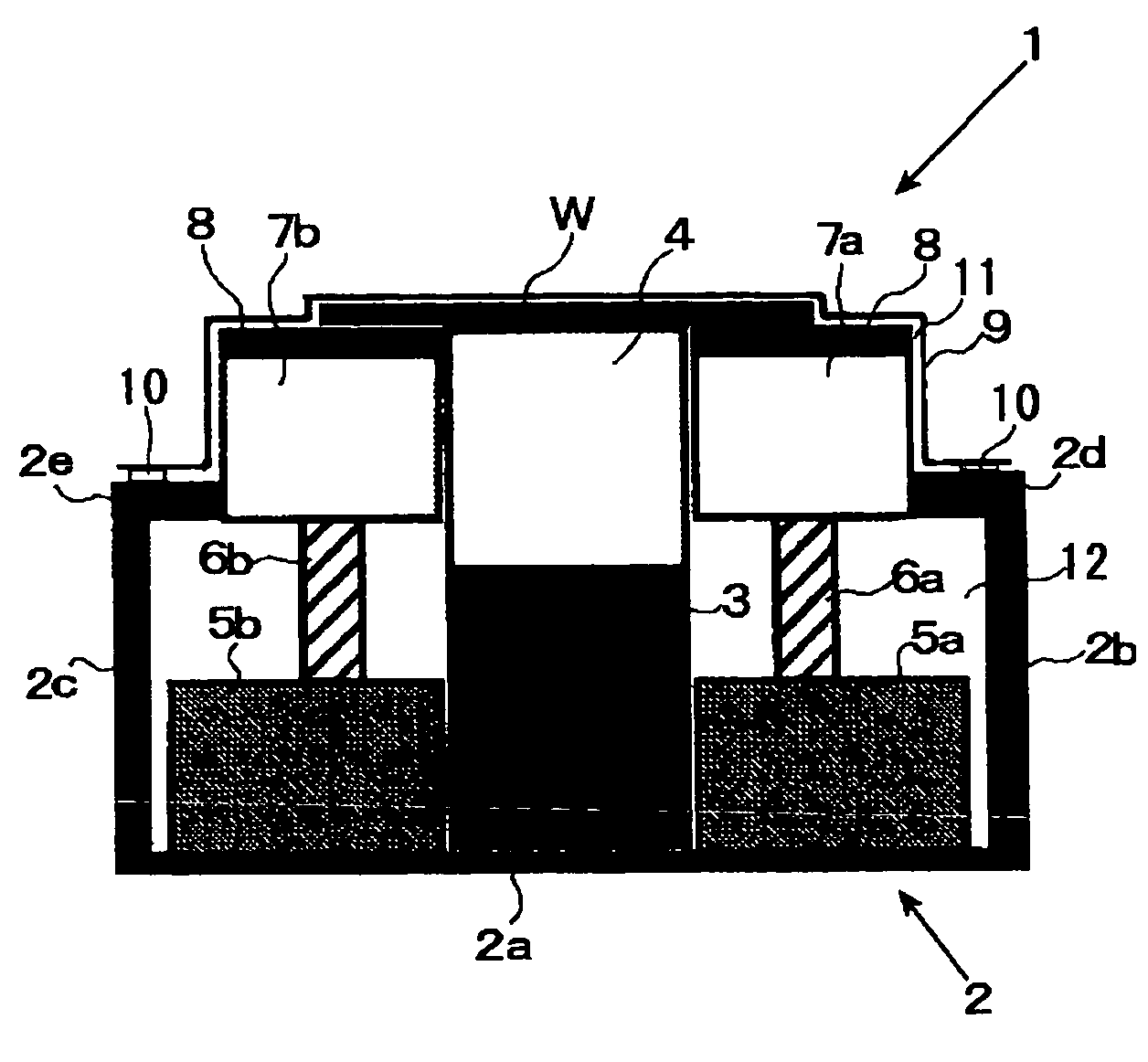
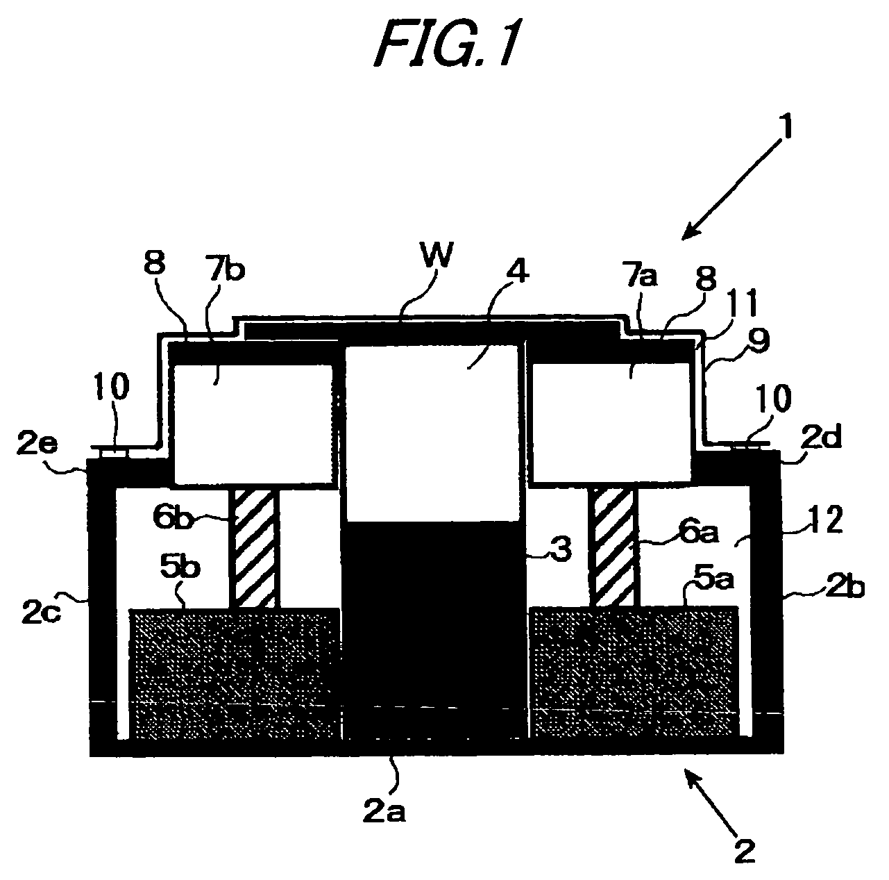
[0008] In accordance with one or more embodiments of the present invention, a folding and forming apparatus of prepreg is provided with: a protruding jig with two flat side surfaces opposed to each other; a pair of lifters respectively provided adjacent to the sides of the protruding jig and capable of moving with respect to the protruding jig; and a pair of heaters respectively arranged on upper faces of the lifters. In addition, the apparatus may further be provided with a suction device for drawing air from a
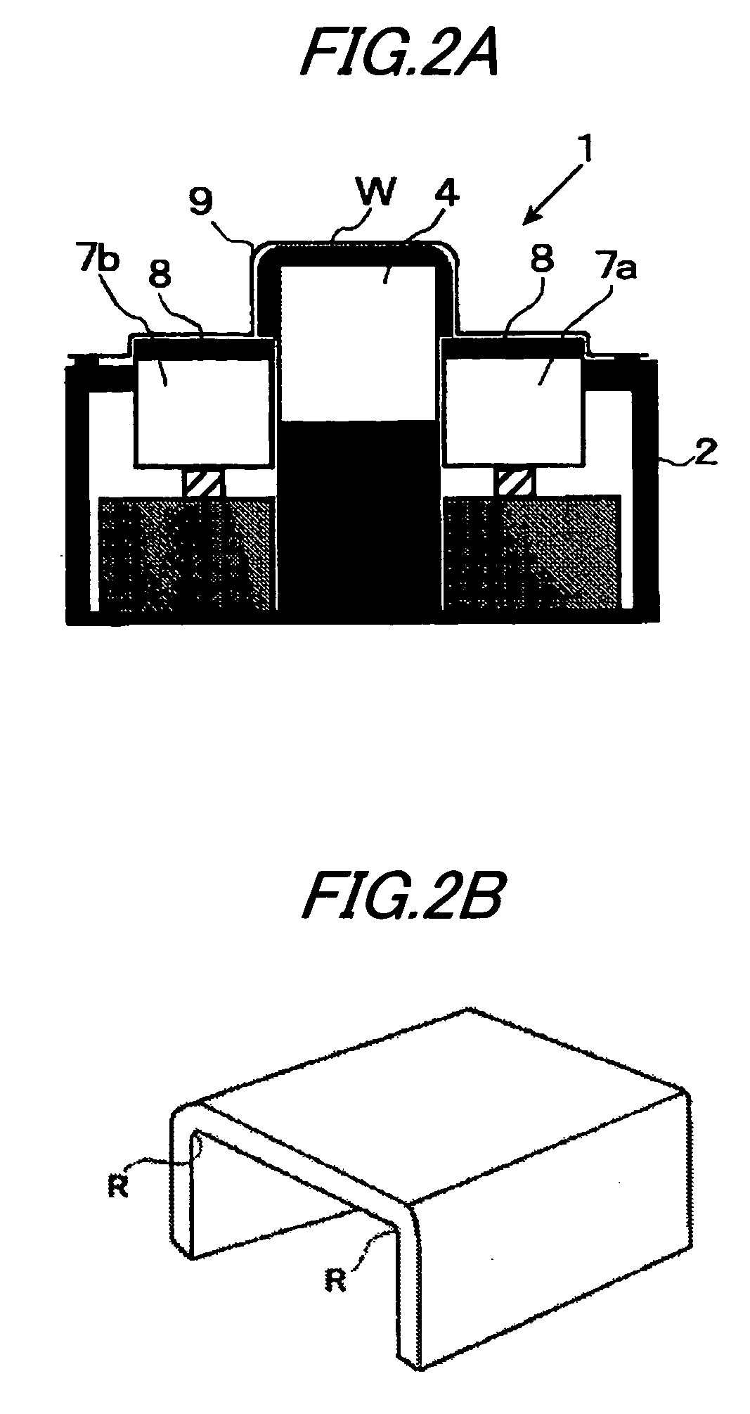
closed space formed by a vacuum bag covering the protruding jig and the lifters. In the apparatus, a prepreg before folding is put on an upper face of the protruding jig and the upper faces of the lifters, and after a portion of the prepreg disposed on at least one of the lifters has been heated and softened, the prepreg is folded and formed. Therefore, a slippage is caused in the folded portion of the prepreg, and the generation of wrinkles can be suppressed. Accordingly, even if a laminated prepreg has a large thickness, it is possible to obtain stable quality. Therefore, of course, such a problem that the running cost is increased due to the prolonged
heating time and the prolonged folding and forming time is not caused, which is unlike the conventional case.
[0009] Further, in accordance with one or more embodiments of the present invention, a folding and forming apparatus of prepreg may further be provided with a box-shaped jig for accommodating the protruding jig and the lifters while upper portions of the protruding jig and the lifters are being protruded from the box-shaped jig. Due to the foregoing, a range of suction by vacuum is limited. Therefore, a period of time necessary for conducting a vacuum suction can be reduced.
[0010] In addition, in accordance with one or more embodiments of the present invention, a method of folding and forming a prepreg is provided with: putting a prepreg on an upper face formed by a protruding jig and a pair of lifters, wherein the protruding jig includes two flat side surfaces opposed to each other and the lifters are respectively arranged adjacent to the sides of the protruding jig; forming a
closed space by covering the upper portion by a vacuum bag; heating and
softening a portion of the prepreg positioned on at least one of the lifters by a heater arranged on the one of the lifters; and lowering the one of the lifters after the portion of the prepreg has been softened, so as to fold and form the prepreg. According to the above method, when a laminated prepreg, even though the thickness of which is large, is folded and formed, it is possible to stably obtain a product of high quality without an increase in the running cost caused by the prolonged heating time and the prolonged folding and forming time.
[0011] According to a folding and forming apparatus and a method of prepreg of one or more embodiments of the present invention, a portion of the prepreg positioned on a lifter, is heated and softened, and then the prepreg is folded and formed. Therefore, a slippage is generated in the folded portion of the prepreg and the occurrence of wrinkles is suppressed. Accordingly, when a layer of prepreg, even though the lamination thickness of which is large, is folded and formed, it is possible to stably obtain a product of high quality without an increase in the running cost caused by the prolonged heating time and the prolonged folding and forming time.

