Method and system for unambiguous angle resolution of a sparse wide-band antenna array

a wide-band antenna array and sparse technology, applied in the field of wide-band antenna arrays, can solve the problems of complex array antennas having unsatisfactory angle resolution, and complex array antennas with a large number of elements, and achieve the effect of avoiding the formation of complex array antennas, reducing the complexity of array antennas, and reducing the cost of array antennas

Active Publication Date: 2006-11-09
TELEFON AB LM ERICSSON (PUBL)
View PDF36 Cites 14 Cited by
  • Summary
  • Abstract
  • Description
  • Claims
  • Application Information

AI Technical Summary

Problems solved by technology

It is complicated or even almost impossible to build classic wide-band array antennas providing good angle resolution.
Thus, there is apparently a contradiction between obtaining a wide bandwidth of the antenna and the array density needed to avoid grating lobes at large scan angles.
Another problem is that array antennas having a large number of

Method used


Image

  • Method and system for unambiguous angle resolution of a sparse wide-band antenna array
  • Method and system for unambiguous angle resolution of a sparse wide-band antenna array
  • Method and system for unambiguous angle resolution of a sparse wide-band antenna array

Examples


second embodiment

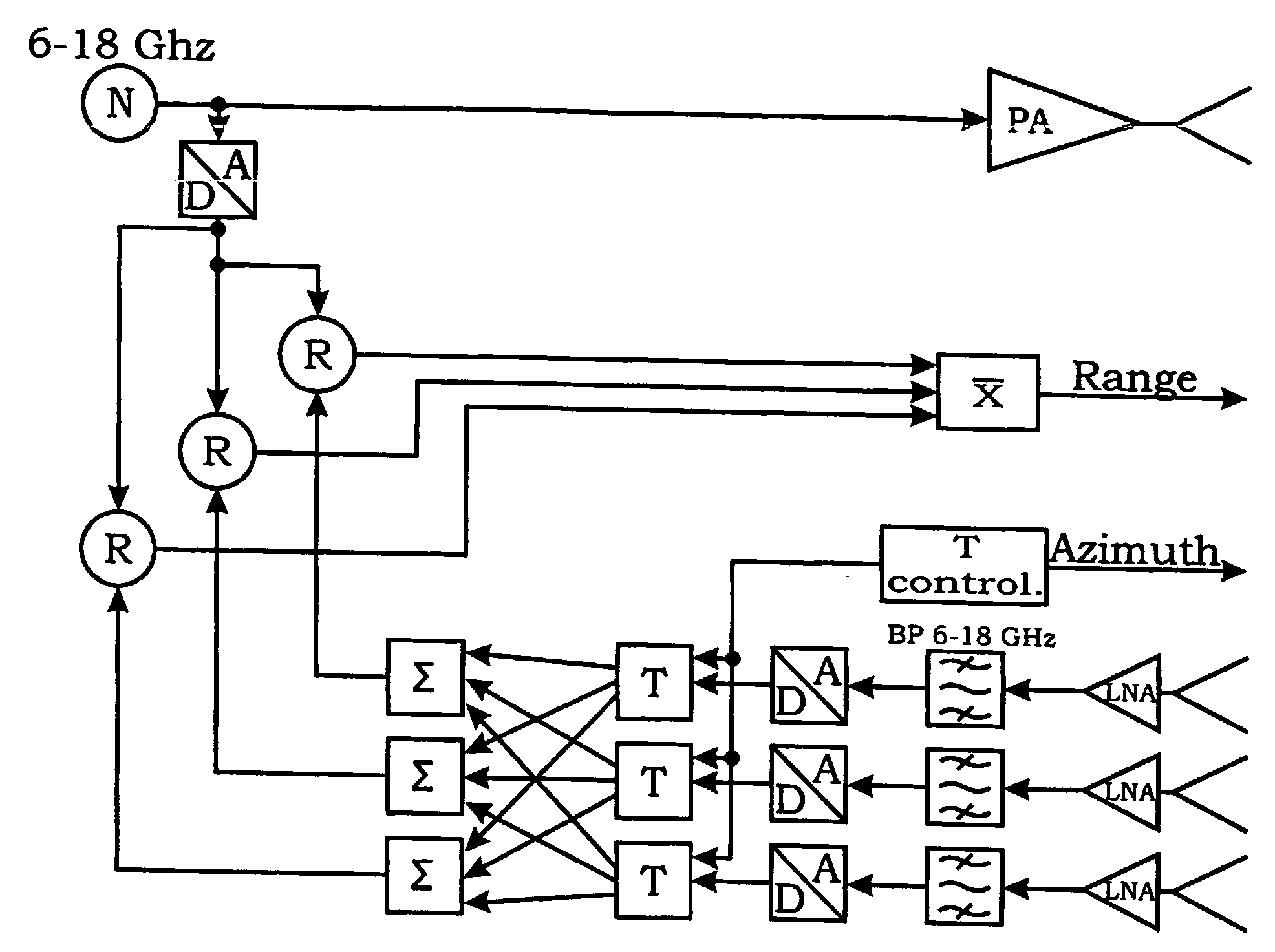
[0033] For the present invention assume a circular array having the main lobe of each antenna element pointing in a radial direction and according to Equation (10) has the simple frequency independent shape: EL⁡(θ)=|cos⁡(θ)ifcos⁡(θ)>00ifcos⁡(θ)≤0(10)

[0034] The sum, from all n receiving antennas then can be written according to Equation (11): EΣ⁡(θ)=∑n=0N-1⁢e⁡(t-2·Rc0+τn⁡(ϕ)-τn⁡(θ))·EL⁡(θ-n·2⁢πN)(11)

[0035] R, φ are distance and bearing to the target, respectively, and θ is the current antenna search angle. Time corrections τn are calculated according to Equation (12): τn⁡(ϕ)=D2·c0·cos⁡(ϕ-n·2⁢πN)(12)

[0036] Expected value of the antenna diagram AP(θ, φ) is calculated according to Equation (13):

AP(θ,φ)=10·log{E[EΣ2(θ,φ)]}  (13)

[0037] Then, we can perform the following calculation: E⁡[EΣ2⁡(θ,ϕ)]=E⁡[(∑n=0N-1⁢e⁡(t-2·Rc0+τn⁡(ϕ)-τn⁡(θ))·EL⁡(θ-n·2⁢πN))2]=E⁡[∑n=0N-1⁢e⁡(t-2·Rc0+τn⁡(ϕ)-τn⁡(θ))·EL⁡(θ-n·2⁢πN)·∑m=0N-1⁢e⁡(t-2·Rc0+τm⁡(ϕ)-τm⁡(θ))·EL⁡(θ-m·2⁢πN)]=E⁡[∑n=0N-1⁢∑m=0N-1⁢e⁡(t-2·Rc0+τn⁡(...

third embodiment

[0038] In yet a third embodiment the antenna array may well be formed as a conformal array and calculated in a similar way corresponding to the above examples of the linear and circular array.

Simulations

[0039]FIG. 3 demonstrates the auto-correlation function for white bandwidth limited noise according to equation (5). As can be seen a bandwidth of 100% is needed to get the sidelobes down to a reasonable level.

[0040] For the simulations 100% bandwidth and a center frequency of 12 GHz was chosen. In other words the frequency range of the radar was 6-18 GHz. The distance to the target is determined by finding the peaks of the convolution between input and output signal.

[0041]FIG. 4 illustrates a simulation result when signal-to-noise was varied. In this case the target is an object, 1 meter long, standing still at a distance of 750 meters. The target area as function of distance is an equally distributed random number per distance sample. The sampling rate in this case was 50 GHz. ...


PUM


Abstract

The present inventive concept for bistatic or monostatic radar utilization discloses a method and a system for unambiguous angle resolution of a sparse wide-band array antenna by utilizing an ultra wide-band signal, generally a wide-band noise signal which may be continuous bandwidth limited white or colored noise. The noise signal is typically generated and radiated by a transmitting antenna covering the entire reception range of a receiving sparse antenna array. An echo signal is received by the sparse receiving array containing n antenna elements, which are generally positioned with separation distances of several wavelengths without creating strong grating lobes due to the type of generated transmit signal. By means of a selected auto-correlation function defining the wide-band noise signal power spectrum, the convolution of the radiated output signal and the received echo input signal will give the target range information, the individual time-delay setting for each antenna element will give an unambiguous angular resolution.

Description

TECHNICAL FIELD [0001] The present invention relates to wide-band antenna arrays, and more particularly to a method and system for unambiguous angle resolution of a sparse wide-band antenna array. BACKGROUND [0002] It is complicated or even almost impossible to build classic wide-band array antennas providing good angle resolution. The reason for this is that the separation of the elements is set by the highest frequency, typically half a wavelength at ƒmax. The physical size of the elements is set by the lowest frequency, typically half a wavelength at ƒmin. Thus, there is apparently a contradiction between obtaining a wide bandwidth of the antenna and the array density needed to avoid grating lobes at large scan angles. [0003] Another problem is that array antennas having a large number of elements will be undesired complex and expensive. Furthermore rotating antennas are generally undesired as that implies further mechanical complexity. From a strategic point of view there is als...

Claims


Application Information

Patent Timeline
IPC IPC(8): G01S13/42G01S13/08G01S7/28G01S13/02H01Q21/08H01Q21/20H01Q21/28
CPCG01S7/2813G01S13/0209H01Q21/28H01Q21/08H01Q21/205G01S2013/0281
Inventor FALK, KENT OLOF
Owner TELEFON AB LM ERICSSON (PUBL)
Why Eureka
Try Eureka