
Wireless apparatus capable of controlling radiation patterns of antenna

a technology of antenna radiation pattern and wireless apparatus, which is applied in the direction of antenna details, antenna feed intermediates, antennas, etc., can solve the problems of interference of transmitted signals on the front-end circuit, degrade communication quality, and the ground plane is not symmetrical to the antenna

Active Publication Date: 2006-11-09
IND TECH RES INST
View PDF6 Cites 36 Cited by
  • Summary
  • Abstract
  • Description
  • Claims
  • Application Information

AI Technical Summary

Benefits of technology

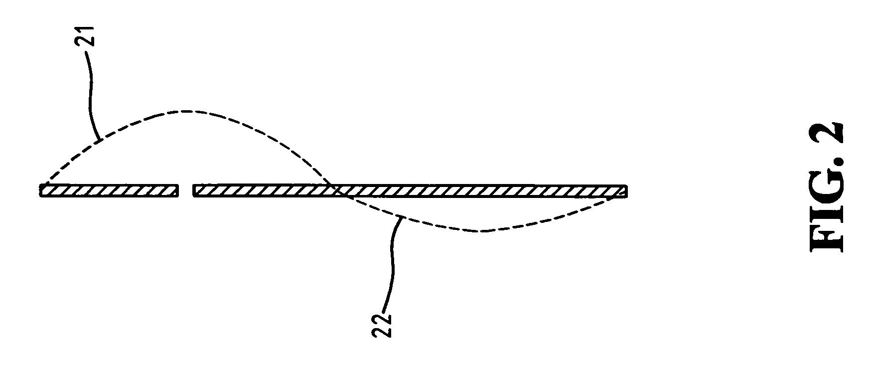
[0007] In a preferred embodiment of the present invention, the angle θ of maximum radiation of antenna is located at θ<90°. The resulting horizontal power gains of the antenna are greater than 0 dBi on both x-z and y-z plane to control radiation pattern and improve antenna's horizontal gain.
[0008] In summary, the wireless apparatus of the present invention has the advantages of simple structure, easy fabrication, and better performance of antenna radiation than the conventional wireless apparatus. The invention can be applied to various kinds of antennas, such as monopole antenna, shorted-monopole antenna, dipole antenna, loop antenna, and planar inverted-F antenna, etc.

Problems solved by technology

Therefore, the ground plane is not symmetrical to the antenna.
This absorption of the radiation energy then degrades the quality of communication.
The transmitted signals on the front-end circuit may be interfered by the radiation energy as well.
This will lead to a poor quality of communication on the horizontal plane (θ=90°).

Method used


Image

  • Wireless apparatus capable of controlling radiation patterns of antenna
  • Wireless apparatus capable of controlling radiation patterns of antenna
  • Wireless apparatus capable of controlling radiation patterns of antenna

Examples


Embodiment Construction

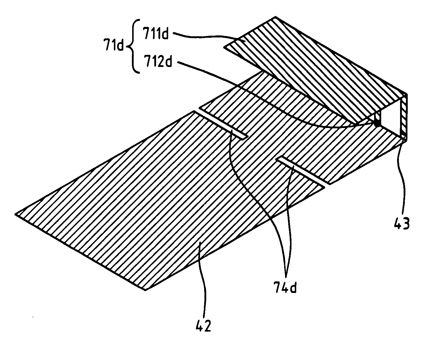
[0022]FIG. 4 shows the structure of a wireless apparatus of the first embodiment of the present invention. The wireless apparatus 40 comprises an antenna element, a ground plane 42, an antenna feed-point 43, and at least one slot or slit formed on the ground plane 42. Both the antenna element and the ground plane 42 are connected to the antenna feed-point 43. Without loss of generosity, the embodiment containing a monopole antenna element 41 and dual slots or slits 44a and 44b is adopted as an example to describe the invention. The dual slots or slits 44a and 44b are formed on the ground plane 42, which are used to suppress the negative current on the ground plane. Therefore, the angle θ of maximum radiation of antenna can be changed from θ>90° to θ<90° . Moreover, the horizontal power gain of antenna can be improved.

[0023]FIG. 5 shows the measured radiation patterns of the first embodiment operated at 2450 MHz according to the first embodiment of the present invention. The antenna...


PUM


Abstract

A wireless apparatus capable of controlling radiation patterns and directions of antenna is provided. It comprises an antenna element, a ground plane, an antenna feed-point, and at least one slot or slit formed on the ground plane. The inclusion of such slots or slits in the wireless apparatus improves the radiation directivity of antenna, and greatly enhances the antenna gain on the horizontal plane. It also resolves the problems caused by shift of radiation patterns of antenna and the poor antenna gains for a conventional antenna apparatus. The wireless apparatus of the present invention has the advantages of simple structure and easy fabrication. The invention can be applied to various kinds of antennas, such as monopole antenna, shorted-monopole antenna, dipole antenna, loop antenna, and planar inverted-F antenna, etc.

Description

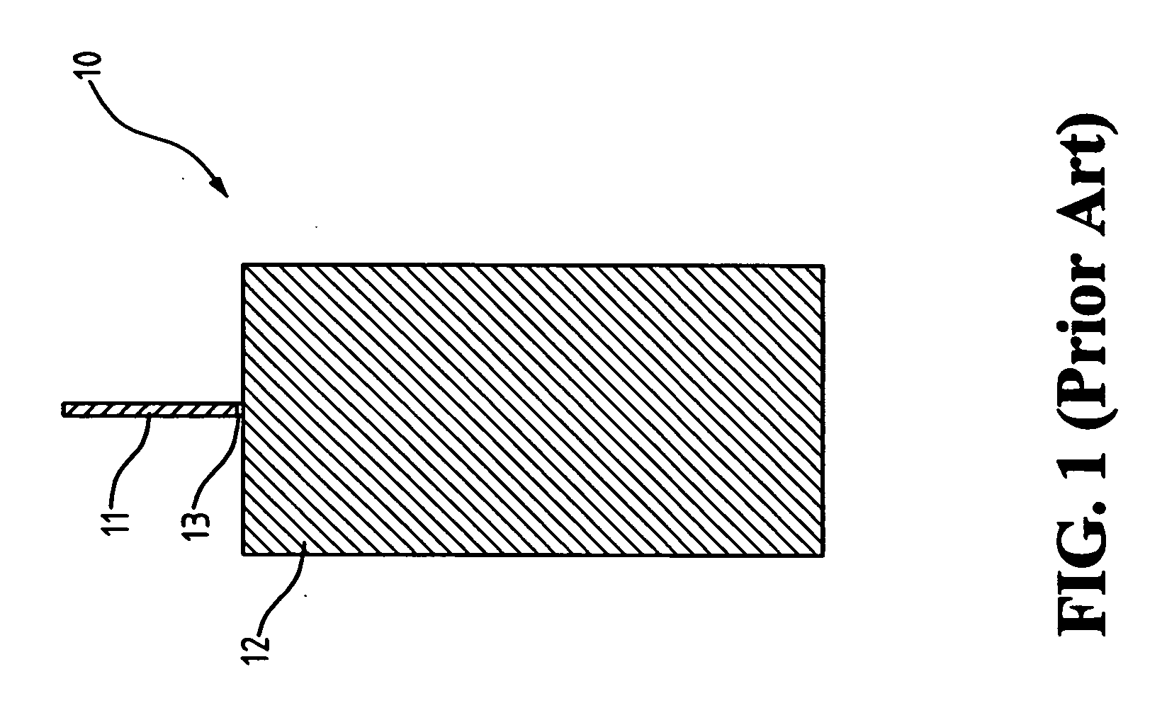
FIELD OF THE INVENTION [0001] The present invention generally relates to a wireless apparatus, especially to a wireless apparatus capable of controlling radiation patterns of antenna BACKGROUND OF THE INVENTION [0002] As the applications of wireless apparatus grow, the radiation patterns of antenna become more and more important in order to improve the communication quality. The antenna of conventional wireless apparatus is usually placed near the edge of the wireless apparatus to reduce the size of the whole system. Therefore, the ground plane is not symmetrical to the antenna. The radiation patterns of antenna are affected by the ground plane. When the antenna is placed near the edge of the wireless apparatus, the radiation angle θ with maximum radiation energy of antenna is normally located at θ>90°. This means that the direction of maximum radiation energy is inclined to the ground plane. The shift of maximum radiation direction due to the above mentioned unsymmetrical ground...

Claims


Application Information

Patent Timeline
IPC IPC(8): H01Q1/24
CPCH01Q1/243H01Q1/48H01Q9/42H01Q9/30H01Q9/16
Inventor YEH, SHIH-HUANGLU, ZIH-HAOTANG, CHIA-LUN
Owner IND TECH RES INST
Learn More