Light module

Active Publication Date: 2006-11-09
LEXTAR ELECTRONICS CORP
View PDF13 Cites 29 Cited by
  • Summary
  • Abstract
  • Description
  • Claims
  • Application Information

AI Technical Summary

Benefits of technology

[0011] In the light module according to the present invention, the heat transferring plate or the heat transferring pipes, the heat dissipating fins, and the light unit are combined to construct a light module, such as a high power LED mo

Problems solved by technology

Thus, uneven heat dissipation and local hot spots tend to occur.
The resulting local high temperature

Method used


Image

  • Light module
  • Light module
  • Light module

Examples


Embodiment Construction

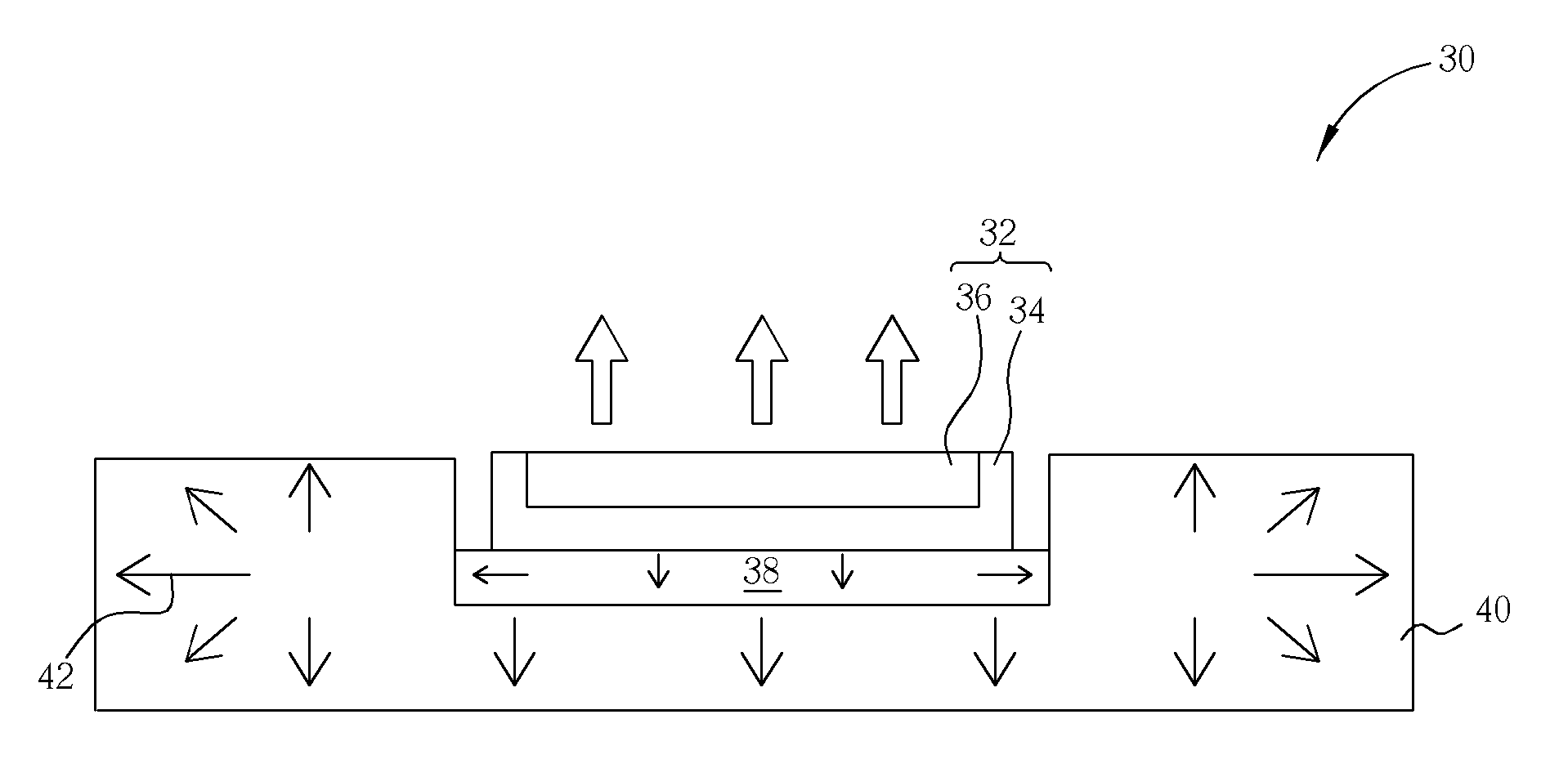
[0021] Please refer to FIG. 3. FIG. 3 is a schematic cross-sectional diagram showing an LED module according to an embodiment of the present invention. As shown in FIG. 3, the light module 30 according to the present invention comprises a light unit 32, a heat transferring plate 38, and a plurality of heat dissipating fins 40.

[0022] The light unit 32 provides a light source and typically comprises a substrate 34 and a light-emitting element 36. The substrate 34 is preferably in a flat shape for correspondingly matching up the shape of the heat transferring plate38. The light-emitting element 36 may be a traditional electric bulb light source, or a packaged LED element, module, or light engine, such as the conventional LED as mentioned above, not limited to lead type or chip type LEDs. The light-emitting element 36 also may be a package body comprising one LED or an aggregate of a plurality of LEDs. The light-emitting element 36 also may be an aggregate comprising a plurality of LED...


PUM


Abstract

A light module comprises a light unit, a heat transferring plate or a plurality of heat transferring pipes, and a plurality of heat dissipating fins. The heat transferring plate or heat transferring pipes are positioned on the bottom surface of the light unit to transfer heat generated by the light unit. When the heat transferring plate is used, the heat dissipating fins are arranged under the heat transferring plate and perpendicular to the bottom surface of the heat transferring plate. The heat dissipating fins have a recess for the accommodation of the heat transferring plate and the light unit. When the heat transferring pipes are used, the heat dissipating fins each contact the heat transferring pipes. Uniform heat dissipation is thus attained.

Description

BACKGROUND OF INVENTION [0001] 1. Field of the Invention [0002] The present invention relates to a light module, and more particularly to a light module having good heat dissipation properties. [0003] 2. Description of the Prior Art [0004] Fluorescent bulb, fluorescent tubes, or electric bulbs are used in traditional light devices as light source generators. In recent years, light-emitting diodes (LED) have been developed as light source generators. LED is a type of cold illumination and has the advantages of low power consumption, long device lifetime, no idling time, and quick response speed. In addition, since the LED also has the advantages of small size, suitability for mass production, and ease of fabrication as a tiny device or an array device, it has been widely applied in display apparatus and indicating lamps used in information, communication, consumer electronic products, and automotive industry, such as, cellular phones, as backlights of personal data assistants, outdoo...

Claims


Application Information

Patent Timeline
IPC IPC(8): F21V29/00
CPCF21K9/00F21S48/328F21V29/004F21V29/006F21Y2101/02Y10S362/80H01L33/648F21V29/763F21V29/77F21V29/773F21V29/85H01L33/642F21V29/51F21V29/70F21V29/89F21Y2115/10F21S45/47
Inventor CHANG, CHIH-CHINHUANG, TENG-HUEILEE, CHIEN-LUNG
Owner LEXTAR ELECTRONICS CORP
Why Eureka
Try Eureka