
Apparatus and method for communicating signaling information

a signaling information and apparatus technology, applied in the field of apparatus and methods for communicating signaling information, can solve the problems of significant interference in the other cell, unoptimized for many other applications, and suspension of uplink resources, so as to achieve alleviation or eliminate the effect of significant interferen

Active Publication Date: 2006-11-09
SONY CORP
View PDF11 Cites 35 Cited by
  • Summary
  • Abstract
  • Description
  • Claims
  • Application Information

AI Technical Summary

Benefits of technology

The invention provides an apparatus for transmitting signaling information in a cellular communication system. The apparatus includes means for generating scheduling assistance data for a base station based scheduler, allocating the scheduling assistance data to a first transport channel, and transmitting the first and second transport channels as multiplexed transport channels on a first physical resource. This improves the performance of the cellular communication system as a whole and the individual performance of the end-users. The invention also allows for flexible signaling and efficient retransmission of data. The first and second transport channels may have different transmission reliabilities, bit error rates, and error correction encoding, allowing for improved performance and trade-offs between data transmission and other system requirements. The invention also provides a practical and low complexity implementation for individual optimization and trade-offs between scheduling assistance data and other data using a common physical resource.

Problems solved by technology

A user for whom the radio path gain to another cell is similar to the radio path gain to the current serving cell may cause significant interference in the other cell.
However, once the packet call has completed (all data to send has been sent and the transmission buffer is temporarily empty), allocation of uplink resources is suspended.
However, although this approach is suitable for many applications it is not optimal for many other applications.
Specifically, the signaling is relatively slow and the allocation response by the RNC scheduler is not particularly fast due to the delays associated with communication between the base station and the RNC (over the lub interface) and the protocol stack delay in receiving the PCR and transmitting the allocation grant message via peer-to-peer layer 3 signaling.
However, as the efficiency of the scheduling activity relies on sufficient information being available, the requirements for the signaling functionality become increasingly severe.
Specifically, the existing approach wherein signaling is transmitted to the RNC by layer 3 signaling, is inefficient and introduces delays which limit the scheduling performance of a base station based scheduler.
In particular, using techniques identical to the prior art (such as the use of PCR messages) are not attractive due to the fact that the transport channels used are terminated in the RNC—the signaling information thus ends up in a different network entity than that in which the scheduler resides and an additional delay is introduced in communicating this to the base station scheduler.
However, some techniques, involving one or more air interface retransmissions, afford an increase in efficiency (and hence capacity) but at the expense of transmission delay.
However, the consequential increased transmission delay may render the approach unsuitable for carrying control signaling information to a base station scheduler and may result in an inefficient scheduling by this scheduler.
However, the air interface transmission delay associated with a retransmission is very high as it includes the delay of the acknowledgement feedback process (e.g. the delay of waiting for a possible acknowledgement before deciding to retransmit) and of the scheduling of a retransmission data packet.
For example, uplink signaling techniques adopted for 3GPP FDD uplink suffer from latencies which, if applied to a TDD uplink system, may significantly degrade the performance of that TDD system with respect to the level of performance that is achievable.

Method used


Image

  • Apparatus and method for communicating signaling information
  • Apparatus and method for communicating signaling information
  • Apparatus and method for communicating signaling information

Examples


Embodiment Construction

[0089] The following description focuses on embodiments of the invention applicable to a UMTS (Universal Mobile Telecommunication System) cellular communication system and in particular to a UMTS Terrestrial Radio Access Network (UTRAN) operating in a Time Division Duplex (TDD) mode. However, it will be appreciated that the invention is not limited to this application but may be applied to many other cellular communication systems including for example a GSM (Global System for Mobile communication system) cellular communication system.

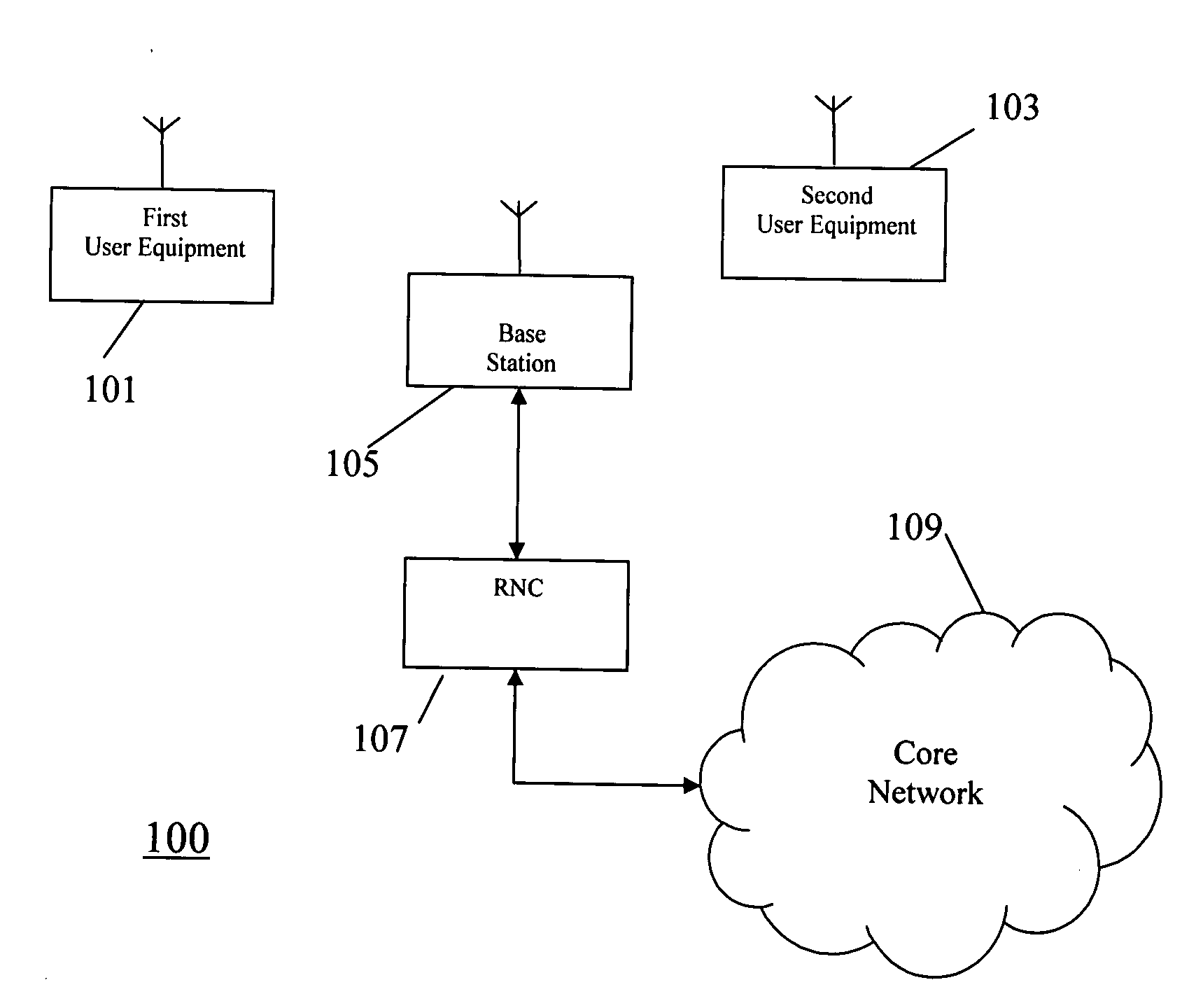
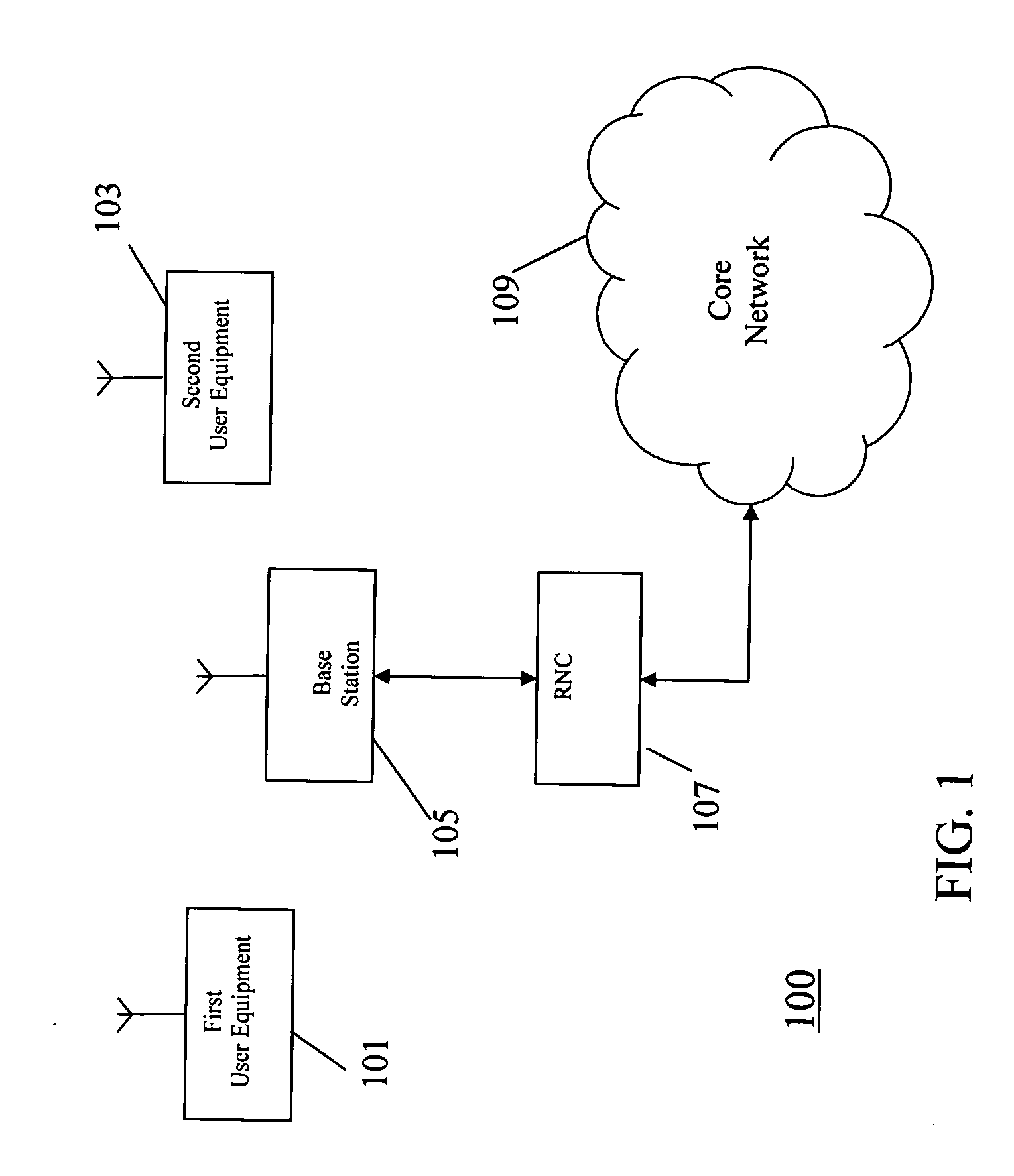
[0090]FIG. 1 illustrates an example of a cellular communication system 100 in which embodiments of the invention may be employed.

[0091] In a cellular communication system, a geographical region is divided into a number of cells each of which is served by a base station. The base stations are interconnected by a fixed network which can communicate data between the base stations. A mobile station is served via a radio communication link by the base sta...


PUM


Abstract

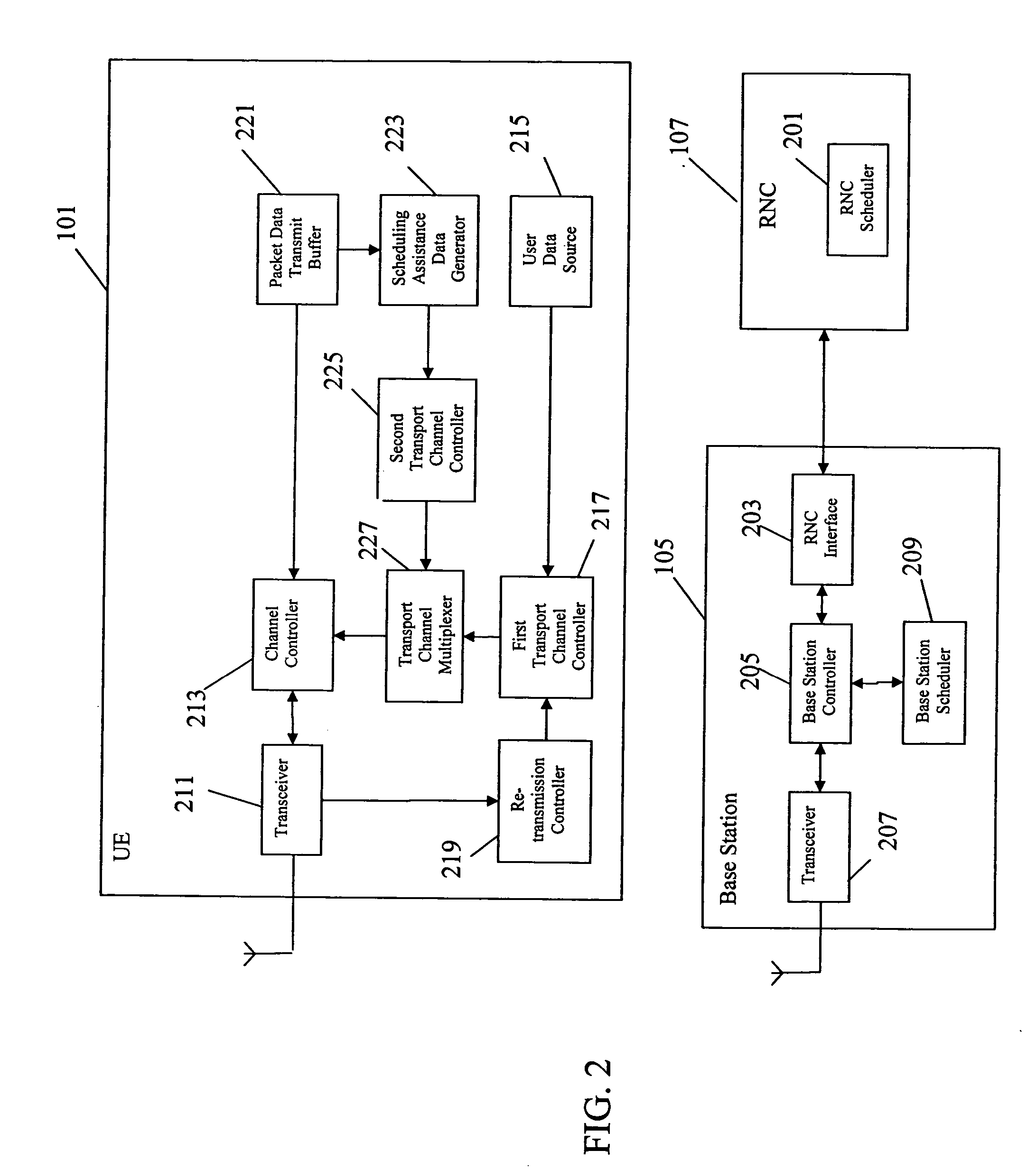
A User Equipment, UE, of a cellular communication system transmits scheduling assistance data to a base station comprising a base station scheduler which schedules packet data. The scheduling assistance data relates to packet data communication of the UE. The scheduling assistance data is generated by a scheduling assistance data generator coupled to a packet data transmit buffer associated with the packet data transmission. A first transport channel controller allocates other data to a first transport channel and a retransmission controller operates a retransmission scheme for this transport channel. A second transport channel controller allocates the scheduling assistance data to a signaling transport channel and a transport channel multiplexer combines the two transport channels as multiplexed channels on a single physical resource. The transmission reliabilities for the retransmission and non-retransmission transport channels may be individually optimized.

Description

CROSS-REFERENCE TO RELATED APPLICATIONS [0001] This application claims benefit of U.K. application GB 0508801.8 filed May 3, 2005. The contents of this document are incorporated herein by reference. TECHNICAL FIELD [0002] The invention relates to signaling of scheduling assistance data in a cellular communication system and in particular, but not exclusively, to signaling in a 3rd Generation Partnership Project (3GPP) cellular communication system. BACKGROUND ART [0003] Currently, 3rd generation cellular communication systems are being rolled out to further enhance the communication services provided to mobile users. The most widely adopted 3rd generation communication systems are based on Code Division Multiple Access (CDMA) and Frequency Division Duplex (FDD) or Time Division Duplex (TDD). In CDMA systems, user separation is obtained by allocating different spreading and / or scrambling codes to different users on the same carrier frequency and in the same time intervals. In TDD use...

Claims


Application Information

Patent Timeline
Patent Type & Authority Applications(United States)
IPC IPC(8): H04Q7/24H04L1/00H04L1/18H04L12/56H04W28/04H04W72/12H04W84/04H04W88/02H04W88/08
CPCH04L1/0041H04L1/0067H04L1/007H04L1/0072H04L1/08H04L1/1867H04W88/08H04L2001/0098H04W28/04H04W72/1268H04W72/1278H04W72/1284H04L47/14H04W72/20H04W72/21H04W8/04H04L1/1812
Inventor ANDERSON, NICHOLAS WILLIAMBEALE, MARTIN WARWICKLEGG, PETER JONATHON
Owner SONY CORP
Learn More