Packet routing apparatus

a packet routing and packet technology, applied in data switching networks, digital transmission, data switching by path configuration, etc., can solve the problems of slow relay speed of packets and slow processing speed of supplementary processors, and achieve the effect of reducing development costs

Inactive Publication Date: 2006-11-09
HITACHI LTD
View PDF16 Cites 42 Cited by
  • Summary
  • Abstract
  • Description
  • Claims
  • Application Information

AI Technical Summary

Benefits of technology

[0010] However, when using the supplementary processor, disclosed as an extended function module in the application mentioned above, the supplementary processor has slow processing speed, since routing is processed by using software. A drawback of slow routing is that the relay speed of the packet becomes slower.
[0019] (2) As in (1), the extended function processing module is connected to the routing module. However, a new interface is provided for the routing module. This interface is different from the interface which the port control module is connected to. Consequently, the extended function processing module connects to the interface. This makes it possible to realize a high-speed extended function module within minimal adaptation.

Problems solved by technology

However, when using the supplementary processor, disclosed as an extended function module in the application mentioned above, the supplementary processor has slow processing speed, since routing is processed by using software.
A drawback of slow routing is that the relay speed of the packet becomes slower.

Method used


Image

  • Packet routing apparatus
  • Packet routing apparatus
  • Packet routing apparatus

Examples


Embodiment Construction

[0047] An embodiment of the present invention will be explained with reference to the drawings.

[0048] The following explanation mainly describes routing processing of a packet routing apparatus. The packet routing apparatus is explained as a router. The packet routing apparatus may, of course, be an apparatus other than a router.

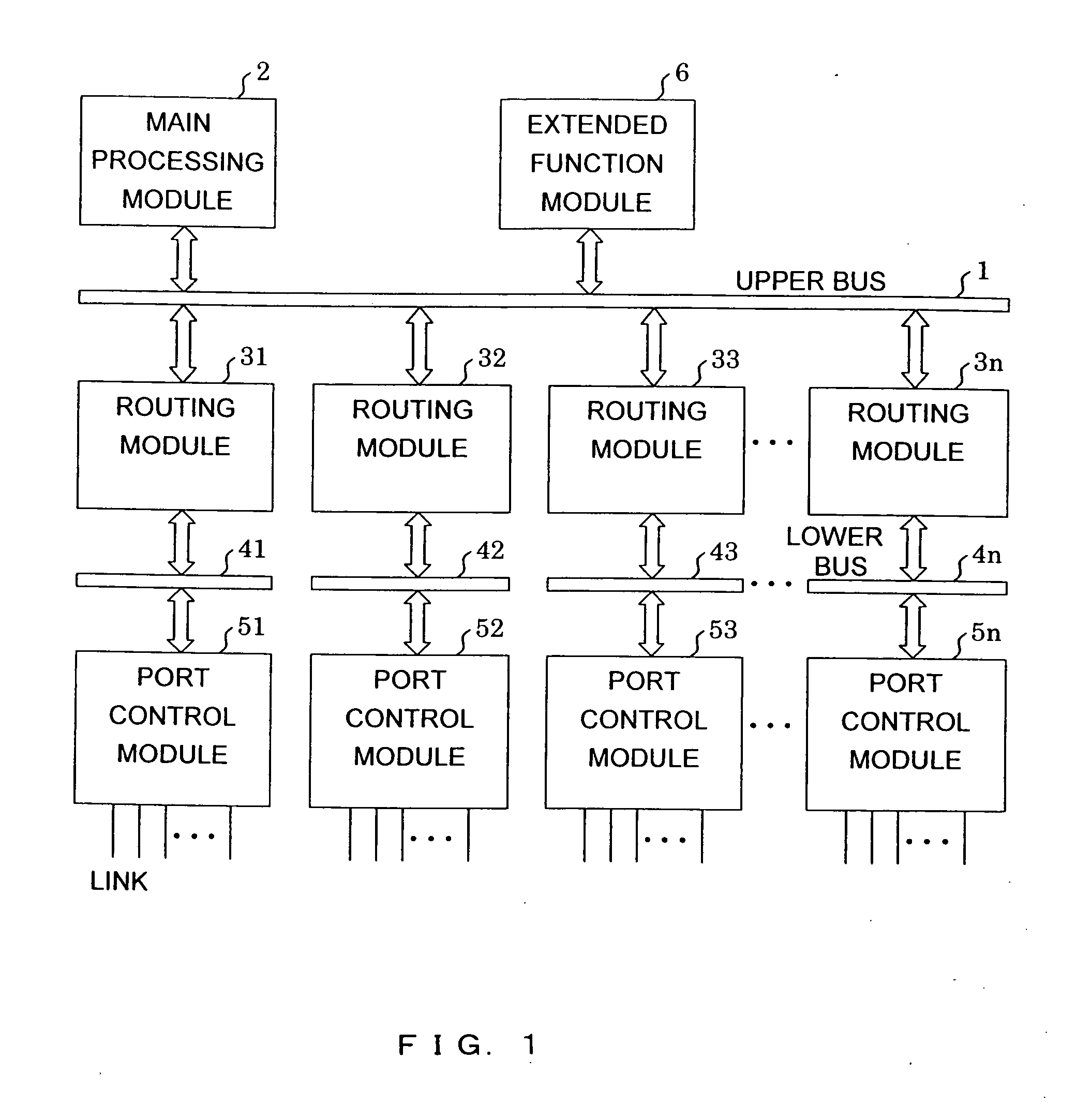
[0049]FIG. 1 is a block diagram of a router wherein an extended function module is connected to an upper BUS. In this router, an extended function module 6 is connected to the upper BUS 1, which connects a plurality of routing modules 51 to 5n.

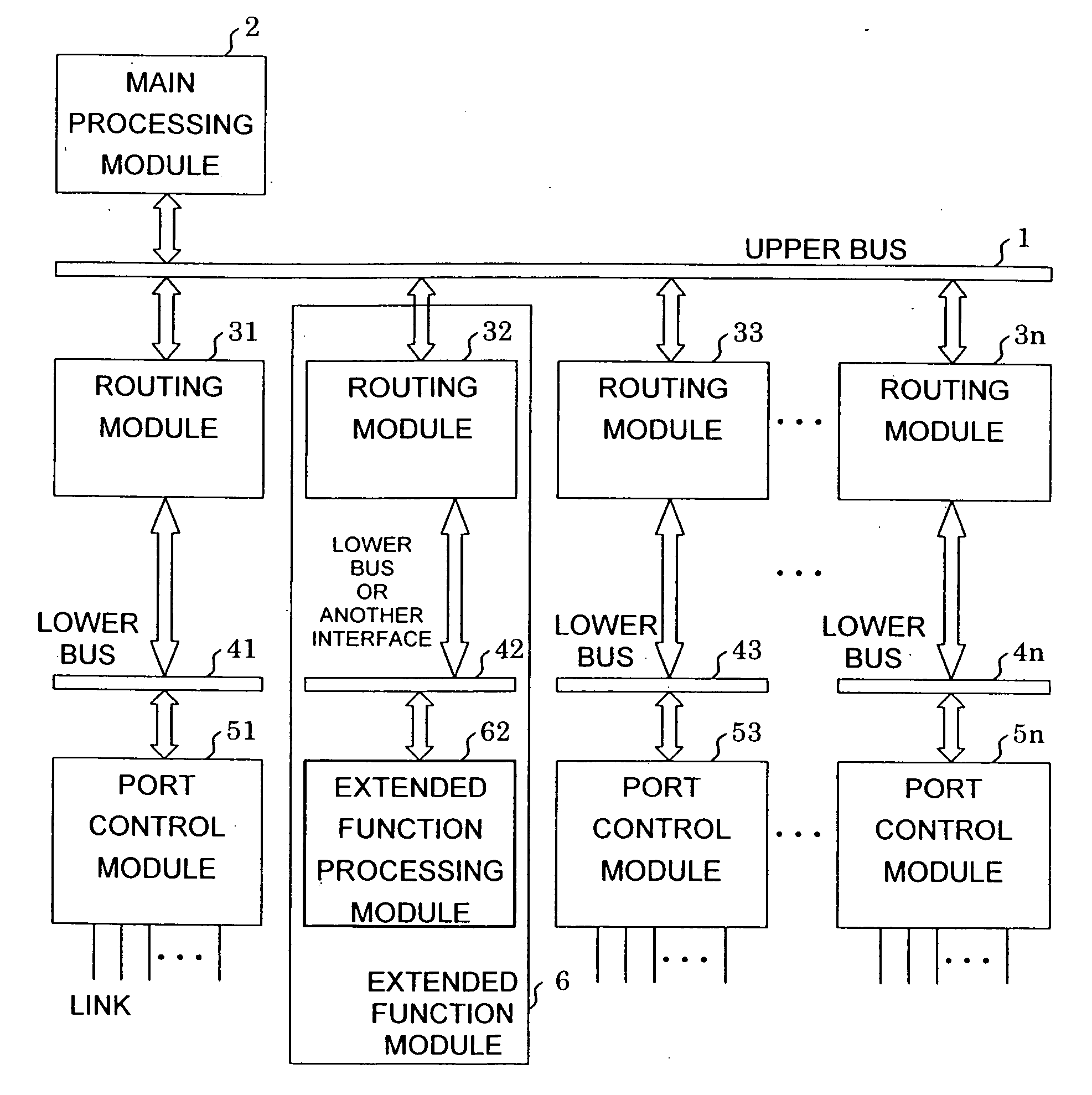
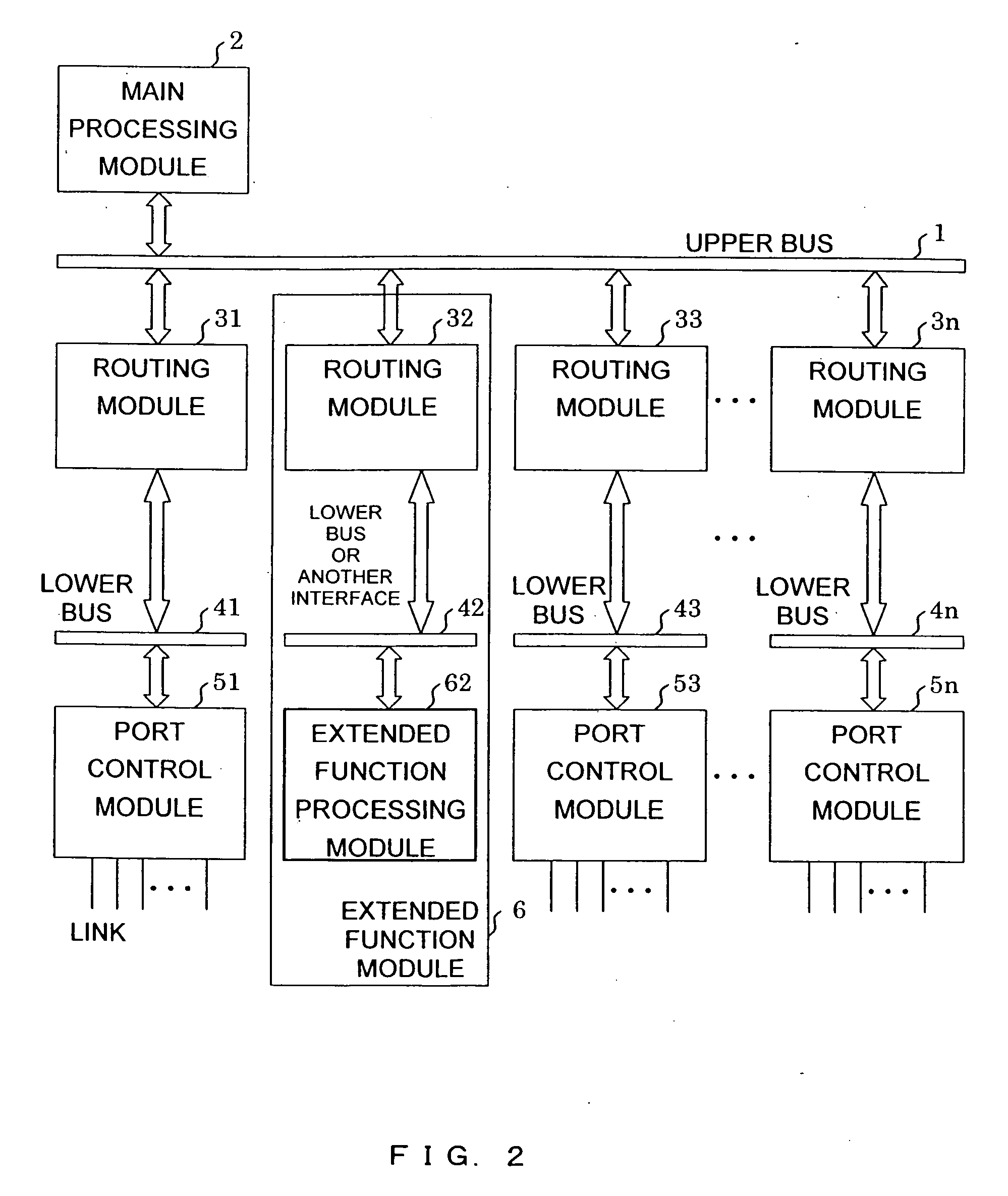
[0050]FIG. 2 is a schematic block diagram showing a router of an embodiment. In this router, an extended function module comprises a routing module and an extended function processing module, connected thereto.

[0051] In FIG. 2, the router comprises the upper BUS 1, a main processing module 2, an extended function module 6, a routing module 31, routing modules 33 to 3n, a lower BUS 41, lower BUS 43 to lower BUS 4n, ...


PUM


Abstract

A packet routing apparatus has a plurality of routing units, connected by a first connecting mechanism. The plurality of routing units comprise a first routing unit, connected to at least one port, and a second routing unit, connected to an extended function processor. The first routing unit transmits a packet, received from the port, to another first routing unit and / or a second routing unit. The second routing unit transmits the packet, received from the first connecting mechanism, to the extended function processor.

Description

[0001] The present application is a continuation of application Ser. No. 10 / 093,525, filed Mar. 11, 2002, the contents of which are incorporated herein by reference. CROSS-REFERENCE TO RELATED APPLICATION [0002] The present application is related to “INTERNETWORKING APPARATUS FOR CONNECTING PLURAL NETWORK SYSTEMS AND COMMUNICATION NETWORK SYSTEM COMPOSED OF PLURAL NETWORK SYSTEMS MUTUALLY CONNECTED”, by K. Onishi et al, Ser. No. 09 / 935,919, filed Aug. 27, 1992, now U.S. Pat. No. 5,434,863; “A PACKET ROUTING APPARATUS AND A METHOD OF ROUTING A PACKET” by Y. Sainomoto et al, Ser. No. 10 / 093,527, filed Mar. 11, 2002 claiming priority on Japanese patent application No. 2001-077607; “NETWORK CONNECTION APPARATUS”, by Y. Inagaki et al, Ser. No. 10 / 093,526, filed Mar. 11, 2002 claiming priority on Japanese patent application No. 2001-067954, the contents of which are each incorporated herein by reference.BACKGROUND OF THE INVENTION [0003] The present invention relates to a packet routing a...

Claims


Application Information

Patent Timeline
Patent Type & Authority Applications(United States)
IPC IPC(8): H04L12/28H04L12/46H04L45/58
CPCH04L12/4625H04L49/102H04L45/58H04L45/00
Inventor YOSHINO, SHIGEKIHIGUCHI, HIDEMITSUIKEDA, NAOYASAINOMOTO, YOSHITAKAINAGAKI, YUKIHIDE
Owner HITACHI LTD
Why Eureka
Try Eureka