Apparatus for measuring jitter and method of measuring jitter

a technology of jitter measurement and measuring apparatus, which is applied in the direction of pulse technique, transmission monitoring, instruments, etc., can solve the problems of inefficient measurement, inability to determine the optimum bandwidth to be observed for measuring jitter in the signal-under-measurement, and inability to accurately measure jitter values

Inactive Publication Date: 2006-11-09
ADVANTEST CORP
View PDF31 Cites 6 Cited by
  • Summary
  • Abstract
  • Description
  • Claims
  • Application Information

AI Technical Summary

Benefits of technology

[0013] Preferably, the bandwidth calculating section has a table storage section for storing a coefficient table that correlates the inclination of the respective spectra with the calculating coefficient, whose value decreases as an absolute value of the inclination of the spectrum become large and the cutoff frequency calculating section calculates the upper cutoff frequency by using the calculating coefficient corresponding to the inclination of the spectrum.

Problems solved by technology

That is, if the bandwidth to be observed is too narrow, the jitter is underestimated and if the bandwidth to be observed is too wide, the jitter is overestimated or it takes an excessive time for the measurement.
However, in the past, the method for determining the optimum bandwidth to be observed for measuring jitter in the signal-under-measurement has been lacking.
Therefore, since the conventional jitter measuring method doesn't use the optimum bandwidth, it suffers from inaccuracy associated with the measured jitter values or inefficient measurements.

Method used


Image

  • Apparatus for measuring jitter and method of measuring jitter
  • Apparatus for measuring jitter and method of measuring jitter
  • Apparatus for measuring jitter and method of measuring jitter

Examples


Embodiment Construction

[0036] The invention will now be described based on preferred embodiments, which do not intend to limit the scope of the invention, but exemplify the invention. All of the features and the combinations thereof described in the embodiments are not necessarily essential to the invention.

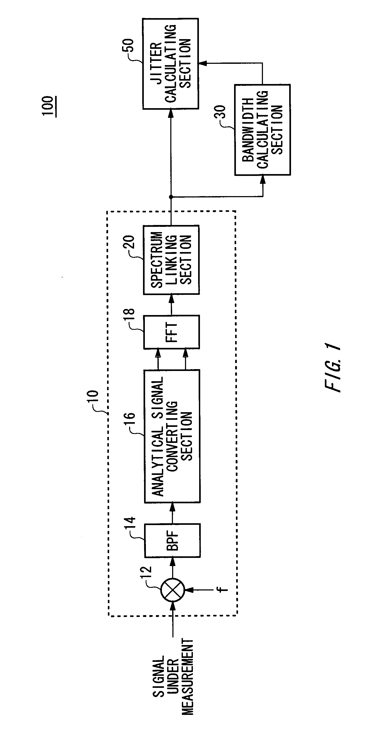
[0037]FIG. 1 is a diagram showing one exemplary configuration of a jitter measuring apparatus 100 according to an embodiment of the invention. The jitter measuring apparatus 100 is an apparatus for measuring jitter such as timing jitter, period jitter and cycle-to-cycle jitter in a signal-under-measurement and has a signal converting section 10, a bandwidth calculating section 30 and a jitter calculating section 50.

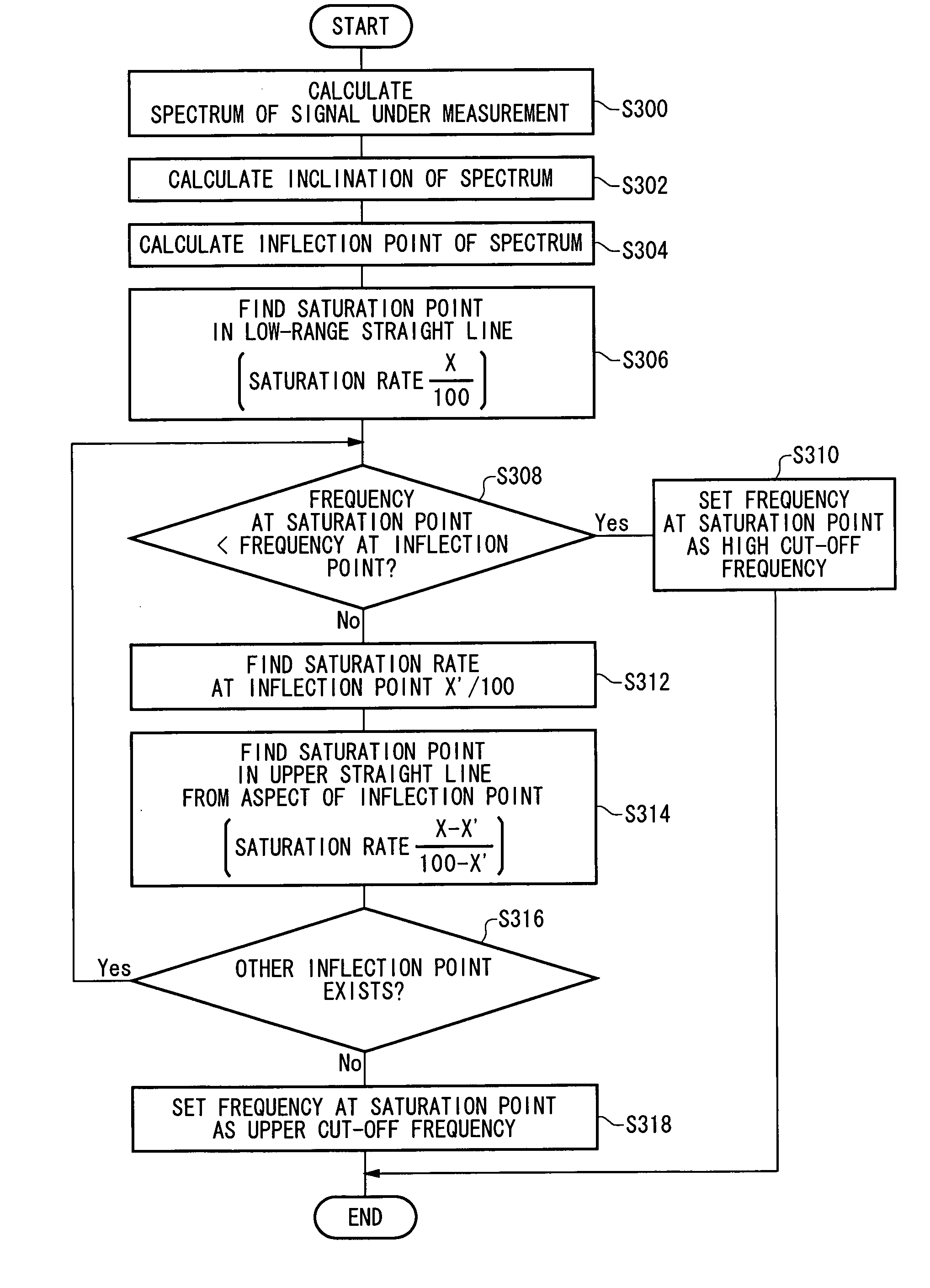
[0038] The signal converting section 10 calculates a spectrum of the signal-under-measurement. In this example, the signal converting section 10 divides a broad frequency band of the signal-under-measurement into a plurality of frequency bands and sequentially calculates the spectra of the...


PUM


Abstract

There is provided a jitter measuring apparatus for measuring jitter in a signal-under-measurement, having a signal converting section for calculating a spectrum of the signal-under-measurement, a bandwidth calculating section for calculating frequency where a saturation rate of a value of the integrated spectrum of the signal-under-measurement becomes almost equal to a saturation rate set in advance in a band-to-be-measured set in advance as upper cutoff frequency of the band-to-be-measured to calculate the jitter and a jitter calculating section for measuring the jitter in the signal-under-measurement based on the spectaum in the band-to-be-measured of the signal-under-measurement.

Description

FIELD OF THE INVENTION [0001] The present invention relates to a jitter measuring apparatus and a jitter measuring method for measuring jitter in a signal-under-measurement. DESCRIPTION OF RELATED ART [0002] Conventionally, period jitter in a signal-under-measurement is being measured by using a frequency counter, a time interval analyzer or the like as fluctuation of zero-crossing time interval of the signal-under-measurement. Because the time interval analyzer also measures jitter by using a built-in frequency counter, those measuring methods are homogeneous in that both of them count time interval. [0003] It is also known to be able to readily measure period jitter by using a time interpolator which is built in a real-time oscilloscope (M. Lauterbach and T. Wey, “Analyze Jitter to Improve High-Speed Design, IEEE Spectrum, pp. 62-67, July 2000). [0004] The present applicant also has proposed a method of converting a signal-under-measurement into an analytical signal, calculating a...

Claims


Application Information

Patent Timeline
Patent Type & Authority Applications(United States)
IPC IPC(8): H04B3/46
CPCG01R31/31709
Inventor YAMAGUCHI, TAKAHIROSOMA, MANIISHIDA, MASAHIRO
Owner ADVANTEST CORP
Why Eureka
Try Eureka