Telescopic shelter system

a shelter system and telescopic technology, applied in the field of shelter systems, can solve the problems of excessive space occupied by the shelter section, difficulty in work, and often cancelled work, and achieve the effects of preventing the separation of one shelter from another, reducing the possession space of the shelter section, and efficient use of the workshop

Inactive Publication Date: 2006-11-16
LEE IN OK
View PDF10 Cites 29 Cited by
  • Summary
  • Abstract
  • Description
  • Claims
  • Application Information

AI Technical Summary

Benefits of technology

[0016] According to the present invention, to order to resolve these problems, an object of the present invention is to provide a telescopic shelter system, whereby several shelter sections arranged on the guide rail in a row can be retracted or expanded, if necessary, possession space of the shelter section can be reduced at a minimum, and it adds the efficient use of the workshop.
[0017] It is a further object of the present invention to provide a telescopic shelter system, whereby extra rails are not needed for the moving allowance of the shelter sections for transferring a production, and the movement of respective shelter sections can be achieved, and also the movement of only the specific shelter section covering the production can be attained in an easy way.
[0018] It is a further object of the present invention to provide a telescopic shelter system, whereby all of shelter sections can be easily telescoped under clear weather, which contribute comfortable working conditions to a work shop.

Problems solved by technology

Therefore, in a shipyard, work is sometimes more difficult due to bad weather such as snow, rain and wind.
Moreover, work is frequently cancelled.
Since the width of respective shelter sections “S” of the conventional art is the same, each shelter section must be arranged in a row, which brings a problem that the space occupied by the shelter section becomes excessively large.
However, when many shelter sections are used, they must be arranged in a row, and a space the same volume as the shelter section is allotted to the other shelters, which leads excessive space.
Furthermore, in the case that the product “W” to be moved is disposed at the middle of the shelter section array, several shelter sections must be moved successively in order to pick up the product “W”, which brings another problem.
Even though the weather is good, work is performed under poor working condition, which leads other problem.
Furthermore, a problem issued by the shelter section's placement on the rail is shown in FIG. 2.
Due to this heavy weight the walls have a tendency to spread away from each other.
Both side walls “P” can not maintain a vertical configuration due to its own weight.
Therefore, it is very difficult that the shelter section is placed on the guide rail “R” because the wheel installed at the bottom end of the shelter section “S” is out of alignment with the guide rail “R”.

Method used


Image

  • Telescopic shelter system
  • Telescopic shelter system
  • Telescopic shelter system

Examples


Embodiment Construction

[0047] This invention will be described in further detail by way of exemplary embodiments with reference to the accompanying drawings.

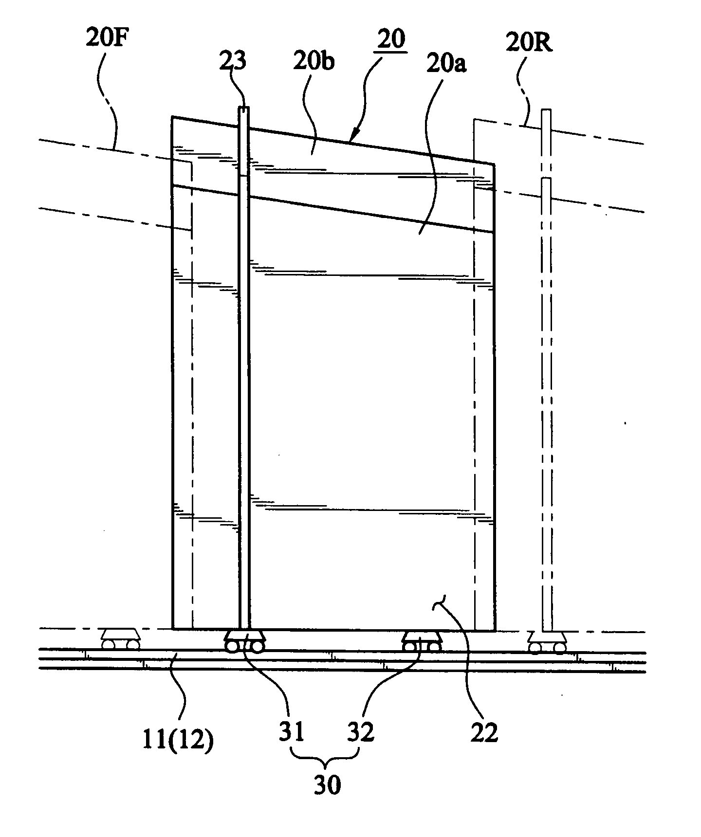
[0048] As shown in FIGS. 3A to 5, the telescopic shelter system is comprised of a guide rail 10 mounted in the ground, several shelter sections 20 arranged in a row along the guide rail 10, telescope along the guide rail 10, a number of wheels 30 provided at the lower portion of each shelter section 20 and travel on the guide rail 10, and a motor 40 mounted on the shelter section 20 for providing a clockwise / counterclockwise movement of the wheel 30.

[0049] The guide rail 10 is comprised of a pair of outer rails 11 arranged in parallel at a certain distance “s1” and a pair of parallel inner rails 12 arranged at an inner side of the outer rails 11, also at a certain distance. The interval between the outer rail 11 and the inner rail 12 exists within the slope of a side wall 20a of the shelter section 20, that is, the slope of the side wall 20a exists ...


PUM


Abstract

A telescopic shelter system comprises two pairs of guide rails having a pair of parallel outer rails and a pair of parallel inner rails arranged at an inner side of the outer rails, a plural of shelters comprising two side walls facing each other and a roof connecting at the top of the two side walls, the two side walls and the roof are tapered at one end of the shelter, each shelter arranged on the guide rail in a row, a plural wheels provided at each lower portion of two side walls of each shelter along movement direction of the shelter, having a pair of first wheel running on the outer rail and a pair of second wheel running on the inner rail, and a motor mounted on the shelter for providing a clockwise-counterclockwise movement of the wheel.

Description

1. FIELD OF THE INVENTION [0001] The present invention relates to a shelter system which is used at an outdoor workshop for large structures, such as an airplane shed, or gymnasium. More particularly, the invention relates to a telescopic shelter system in which several shelter sections are arranged in a row, and can be retracted or expanded, if necessary. 2. BACKGROUND OF THE INVENTION [0002] Since large articles are used at a shipyard, or a steel fabrication plant, the manufacturing process is held mainly outdoors depending the working environment and it also adds convenience of transfer and handling. [0003] A large vessel structure has a heavy weight and an extra large size which varies from few to several meters. The transfer and handling of the production is achieved by a large crane, which also includes a welding process, which is better suited for the outdoor environment. [0004] Therefore, in a shipyard, work is sometimes more difficult due to bad weather such as snow, rain a...

Claims


Application Information

Patent Timeline
Patent Type & Authority Applications(United States)
IPC IPC(8): E04B1/343
CPCE04B1/34368E04B1/34305E04B1/3455B42D5/043B42D5/042
Inventor LEE
Owner LEE IN OK
Why Eureka
Try Eureka