Mobile gas turbine engine and generator assembly

US20060254281A1Inactive Publication Date: 2006-11-16GENERAL ELECTRIC CO

Image

  • Mobile gas turbine engine and generator assembly
  • Mobile gas turbine engine and generator assembly
  • Mobile gas turbine engine and generator assembly

Examples


Embodiment Construction

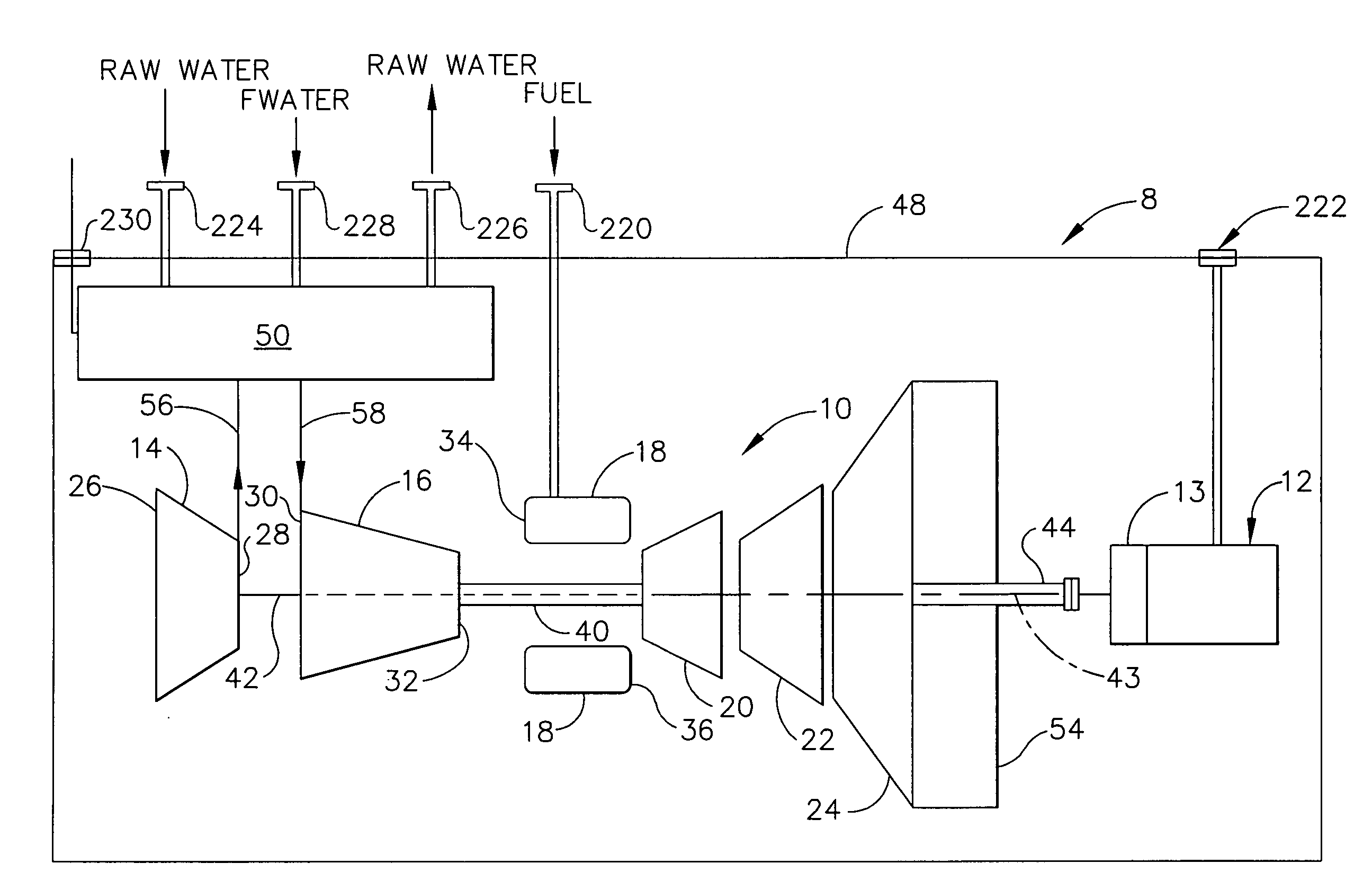
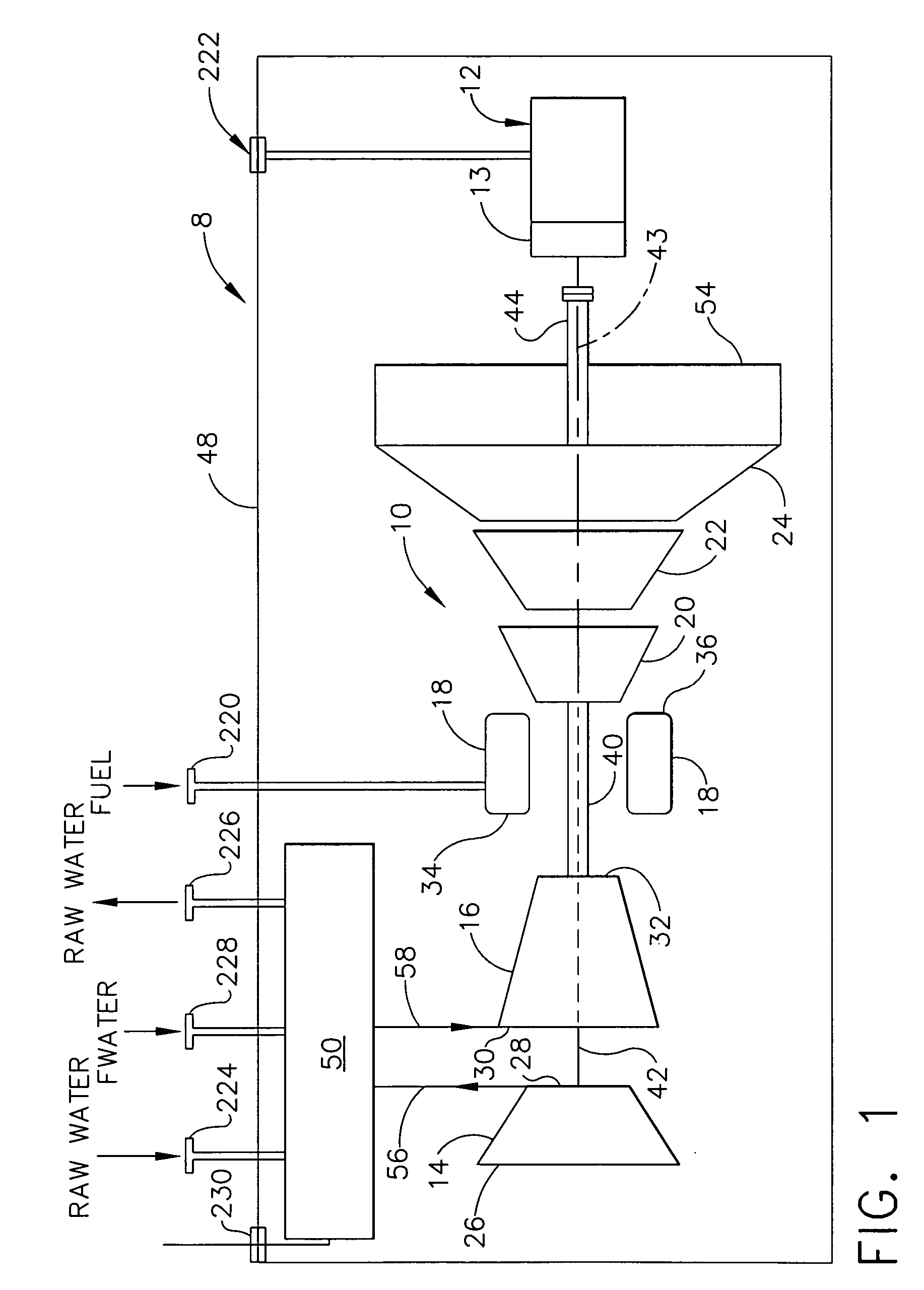
[0010]FIG. 1 is a block diagram of a mobile generator assembly 8 that includes an exemplary gas turbine engine 10 in an installation wherein engine 10 is used to power a load such as an electric generator which is generally represented at 12. Generator 12 may be driven through a gearbox section 13. Hereinafter, references to generator 12 shall be understood to also include gearbox section 13. Gas turbine engine 10 includes, in serial flow relationship, a low pressure compressor or booster 14, a high pressure compressor 16, a combustor 18, a high pressure turbine 20, a low pressure, or intermediate, turbine 22, and a power turbine 24. In one embodiment, combustor 18 is a standard annular can (SAC) combustor that is operable utilizing a water configuration with nitrogen oxides (NOx) abatement. In another embodiment, combustor 18 is a dry low emission (DLE) combustor.

[0011] Low pressure compressor or booster 14 has an inlet 26 and an outlet 28. High pressure compressor 16 has an inlet...


PUM


Abstract

A method for supplying power to a remote load includes coupling a gas turbine engine to a vessel that is not used to provide propulsion for the vessel, coupling a generator to the gas turbine engine, coupling an intercooler system downstream from a first compressor such that compressed air discharged from the first compressor is channeled therethrough, the intercooler system includes an intercooler and a first heat exchanger, channeling a first working fluid through the intercooler to facilitate reducing an operating temperature of air discharged from the intercooler to a second compressor, channeling a second working fluid flowing through the first heat exchanger to extract energy from the first working fluid to facilitate reducing an operating temperature of the first working fluid, and operating the gas turbine engine and generator to supply power to a load that is located remotely from the vessel.

Description

BACKGROUND OF THE INVENTION [0001] This invention relates generally to gas turbine engine and, more particularly to, a portable gas turbine engine generator set. [0002] Gas turbine engines generally include, in serial flow arrangement, a high-pressure compressor for compressing air flowing through the engine, a combustor in which fuel is mixed with the compressed air and ignited to form a high temperature gas stream, and a high pressure turbine. The high-pressure compressor, combustor and high-pressure turbine are sometimes collectively referred to as the core engine. Such gas turbine engines also may include a low-pressure compressor, or booster, for supplying compressed air to the high pressure compressor. [0003] Gas turbine engines are used in many applications, including in aircraft, power generation, and marine applications. The desired engine operating characteristics vary, of course, from application to application. Accordingly, at least one known gas turbine includes a boost...

Claims


Application Information

Patent Timeline
16 Nov 2006
Publication
US20060254281A1
IPC
F02C7/143
CPC
F02C6/203; F02C7/143; F05D2220/76; F05B2240/931; Y02T50/675; F02C7/16; Y02T50/60
Inventors
BADEER, GILBERT HENRY; JOSHI, NARENDRA DIGAMBER