Rotary valve system and engine using the same

a technology of rotary valves and valve timing, which is applied in the direction of oscillatory slide valves, machines/engines, mechanical equipment, etc., can solve the problems of obstructing the flow of both fuel mixture and exhaust gases, destroying the engine, and difficult to vary the valve timing with poppet valves

Inactive Publication Date: 2006-11-16
ZAJAC OPTIMUM OUTPUT MOTORS
View PDF72 Cites 8 Cited by
  • Summary
  • Abstract
  • Description
  • Claims
  • Application Information

AI Technical Summary

Benefits of technology

[0016] In an embodiment for controlling communication between ports in two chambers of an internal combustion engine, the first valve member has first and second openings that move into and out of communication with the two ports, the second valve member has first and second openings which at least partly overlap with respective ones of the first and second openings in the first valve member, and the control adjusts the relative rotational positions of the valve members to change the degree of overlap between the openings and thereby control the timing and duration of communication between the two chambers.

Problems solved by technology

Although widely used in automotive engines and other internal combustion engines, conventional poppet valves have a number of limitations and disadvantages.
Valve float can also be a problem, and if a valve ever does get sucked into a cylinder, it can destroy the engine.
Poppet valves may require periodic adjustment, and typically have relatively large heads which can obstruct the flow of both the fuel mixture and the exhaust gases.
In addition, it is very difficult to vary the valve timing with poppet valves.
However, they also have had limitations and disadvantages which have limited their usefulness.

Method used


Image

  • Rotary valve system and engine using the same
  • Rotary valve system and engine using the same
  • Rotary valve system and engine using the same

Examples


Embodiment Construction

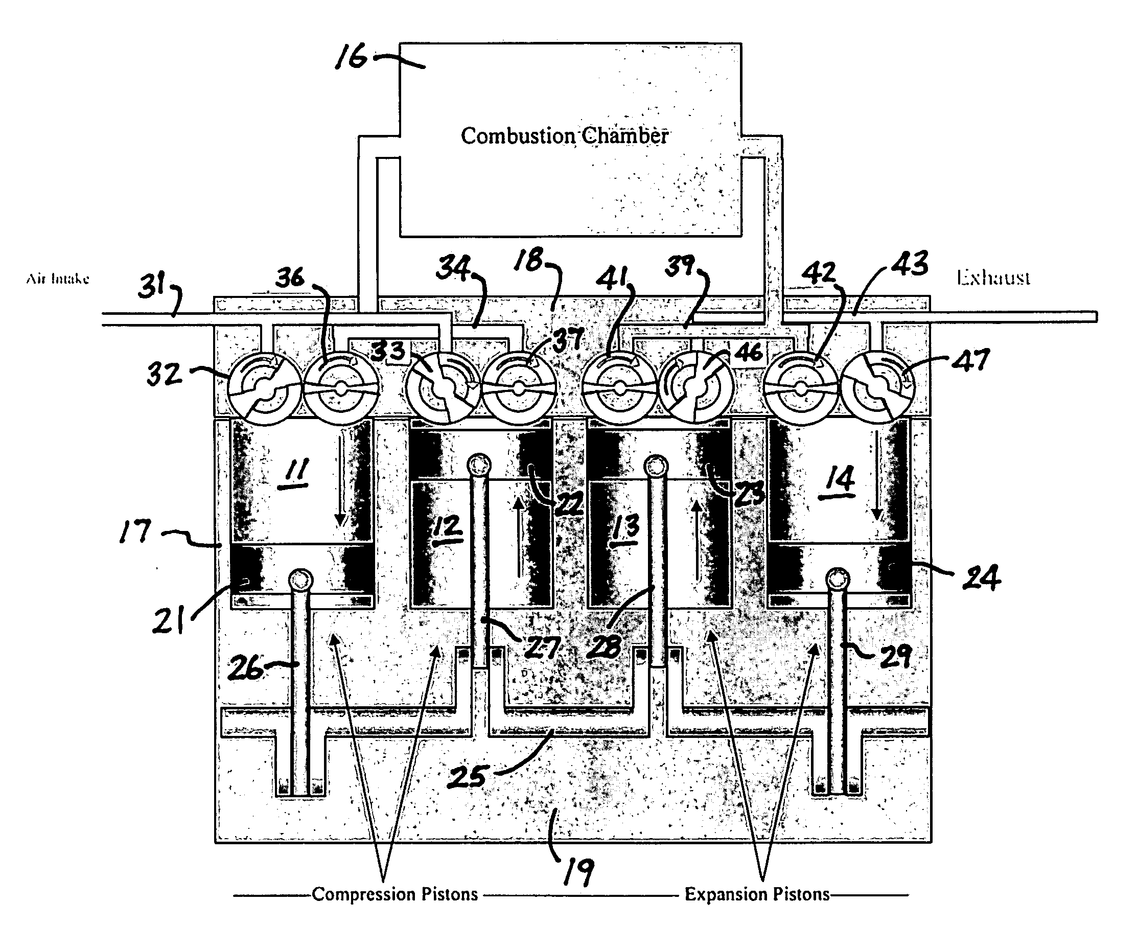
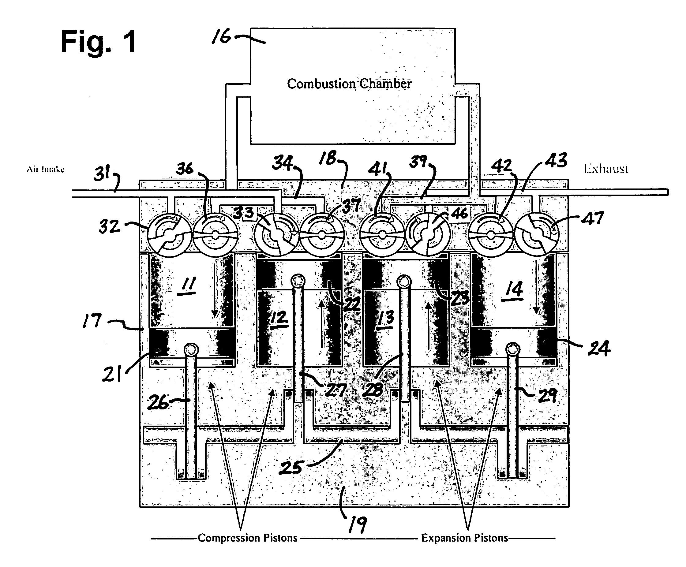
[0030] In the drawings, the invention is illustrated in conjunction with a four cylinder internal combustion engine which is described in greater detail in copending application Ser. No. ______ (Attorney Docket No. A-71789), filed of even date, the disclosure of which is incorporated herein by reference. That engine has a pair of compression cylinders 11, 12 and a pair of expansion cylinders 13, 14 connected to opposite ends of a combustion chamber 16 which can, for example, be of a type disclosed in copending application Ser. No. ______ (Attorney Docket No. A-75041), filed of even date, the disclosure of which is incorporated herein by reference. The cylinders are formed in an engine block 17, with the upper ends of the cylinders being closed by a cylinder head 18 and the lower ends of the cylinders opening into a crankcase 19 in the lower portion of the engine block.

[0031] Reciprocating pistons 21-24 are mounted in the cylinders and connected to a crankshaft 25 by connecting rods...


PUM


Abstract

Rotary valve system for controlling communication with a port in an internal combustion engine which, in one disclosed embodiment, has a crankshaft, compression and expansion pistons connected to the crankshaft for reciprocating movement within compression and expansion chambers, a combustion chamber in which air from the compression chamber is combined with fuel and burned to produce an increased gas volume. The valve system has an outer valve member which is rotatively mounted in a bore and has an opening which moves into and out of communication with the port as the outer valve member rotates, an inner valve member rotatably mounted within the outer outer valve member with an opening at least partly overlapping the opening in the outer valve member, a flange extending along one edge of the opening in the inner valve member and through the opening in the outer valve member for sealing engagement with the wall of the bore, and means for effecting rotation of the valve members to change the degree of overlap between the openings and thereby control the timing and duration of communication between the openings and the port.

Description

RELATED APPLICATION [0001] Provisional Application No. 60 / 660,045, filed Mar. 9, 2005, [0002] Provisional Application No. 60 / 660,046, filed Mar. 9, 2005, [0003] Provisional Application No. 60 / 660,050, filed Mar. 9, 2005, [0004] Provisional Application No. 60 / 760,478, filed Jan. 20, 2006, [0005] Provisional Application No. 60 / 760,641, filed Jan. 20, 2006, [0006] Provisional Application No. 60 / 760,642, filed Jan. 20, 2006, the priority of which are claimed.BACKGROUND OF THE INVENTION [0007] 1. Field of Invention [0008] This invention pertains generally to internal combustion engines and, more particularly, to a rotary valve system and an internal combustion engine utilizing the same. [0009] 2. Related Art [0010] Although widely used in automotive engines and other internal combustion engines, conventional poppet valves have a number of limitations and disadvantages. With the strong springs required to close them and hold them shut and the camshafts, rocker arms, and / or other mechanism...

Claims


Application Information

Patent Timeline
Patent Type & Authority Applications(United States)
IPC IPC(8): F01L7/00
CPCF01B31/14Y02T10/32F01L1/024F01L1/026F01L1/34F01L1/352F01L7/021F01L7/026F01L7/027F01L7/16F01L13/0005F01L13/0015F01L2101/02F01L2800/00F01L2820/01F01L2820/032F02B15/00F02B33/06F02B41/00F02B41/02F02B41/06F02B75/40F02D15/04F02F3/28F02G1/02Y02T10/12Y02T10/14Y02T10/42F01L1/022F01L2301/02Y02T10/40
Inventor ZAJAC, JOHNSMITH, IAN F.
Owner ZAJAC OPTIMUM OUTPUT MOTORS
Why Eureka
Try Eureka