Co-linear tensioner and methods of installing and removing same

a tensioner and co-linear technology, applied in the direction of drilling pipes, drilling/well accessories, sealing/packing, etc., can solve the problems of high maintenance cost, unproven cost effectiveness, and high maintenance cost of conventional tensioning systems, so as to reduce the amount of time that the wellhead is “idling” and install the tensioner faster and safer, eliminate the offset and the resulting unequal load

Active Publication Date: 2006-11-16
CONTROL FLOW
View PDF8 Cites 8 Cited by
  • Summary
  • Abstract
  • Description
  • Claims
  • Application Information

AI Technical Summary

Benefits of technology

[0016] The tensioners and the methods of the present invention, when compared with previous tensioners and methods, have the advantages of: providing relatively quicker and safer installation of tensioners and other equipment; providing flexibility in location of equipment in fluid communication with the tensioners; eliminating offset and the resulting unequal loading in the event one or more of the tensioning cylinders fail; providing a system that is modular in construction, transportation, and assembly; providing interchangeability with other drilling or production facilities; reducing the amount of time that the wellhead is “idle,” i.e., that either a drilling riser or production riser is in use by facilitating quick and easy installation of the tensioner, rotary table, and workover equipment; providing sufficient tension to the long string of the riser in deepwater over extended periods of time; providing a means to maintain the riser in constant tension, with, if necessary, overpull, while the riser is in service; providing the capability to accommodate angular offset between the riser and the vessel induced by vessel motion; and providing the capability to accommodate axial torque induced in the riser string in the event the drilling or production vessel rotates around the wellhead due to weather and sea conditions.

Problems solved by technology

These conventional type tensioning systems have required high maintenance during normal operations due to the constant motion producing wear and degradation of the wire rope members.
Replacing the active working sections of the wire rope by slipping and cutting raises safety concerns for personnel and has not proven cost effective.
In addition, available space for installation and, the structure necessary to support the units including weight and loads imposed, particularly in deep water applications where the tension necessary requires additional tensioners poses difficult problems for system configurations for both new vessel designs and upgrading existing vessel designs.
Other problems unaddressed by these prior tensioners include the location of workover and other equipment placed in-line with the production or drill string and the high cost, labor, and increased safety concerns posed with the installation and removal of these tensioners.

Method used


Image

  • Co-linear tensioner and methods of installing and removing same
  • Co-linear tensioner and methods of installing and removing same
  • Co-linear tensioner and methods of installing and removing same

Examples


Embodiment Construction

[0026] In one aspect, the invention comprises elements that when assembled form a unitary co-linear tensioner. The tensioner may be used to replace both conventional and direct acting tensioning systems. Further, variations of the tensioner may be utilized in both drilling and production riser applications.

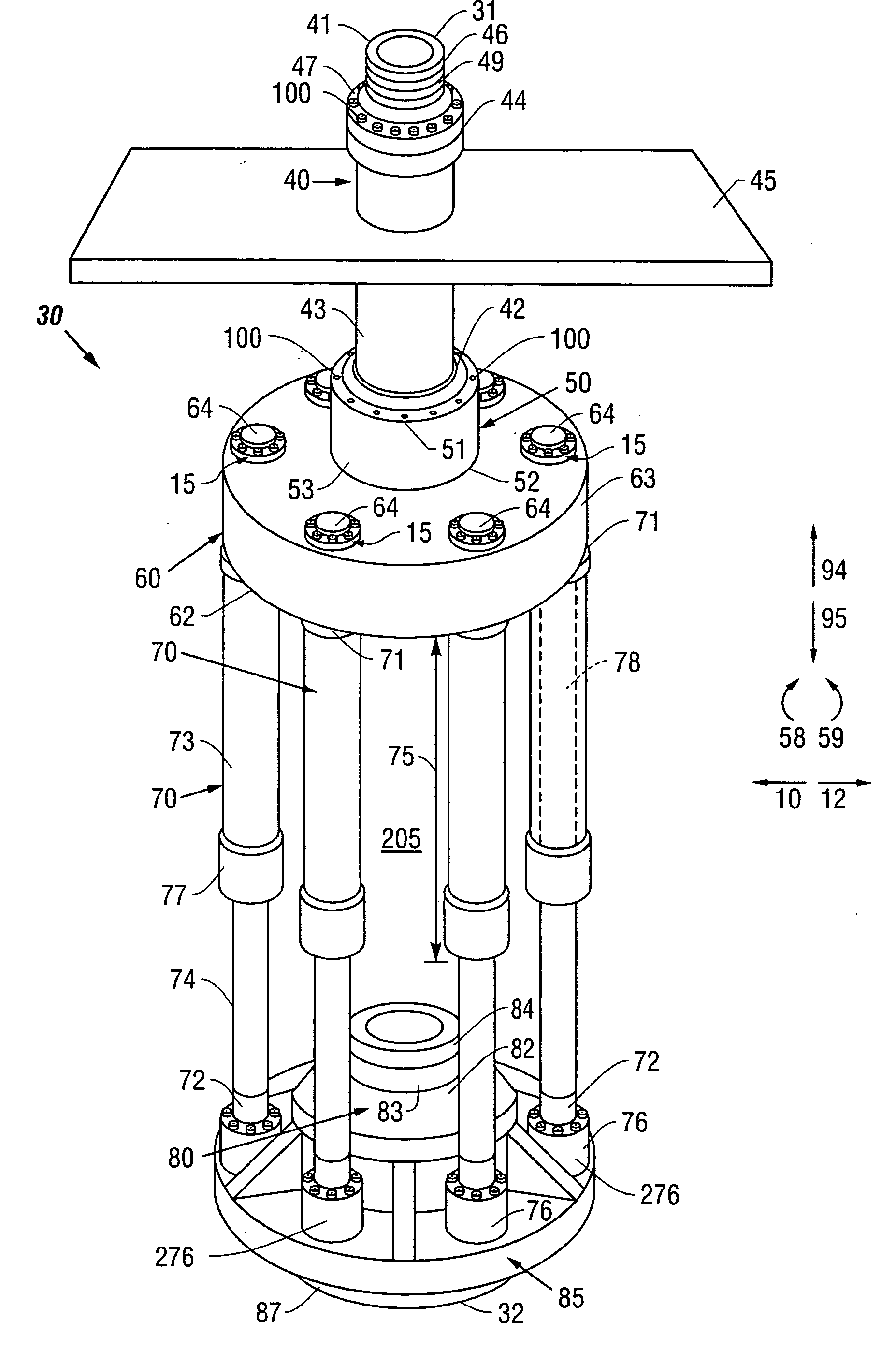
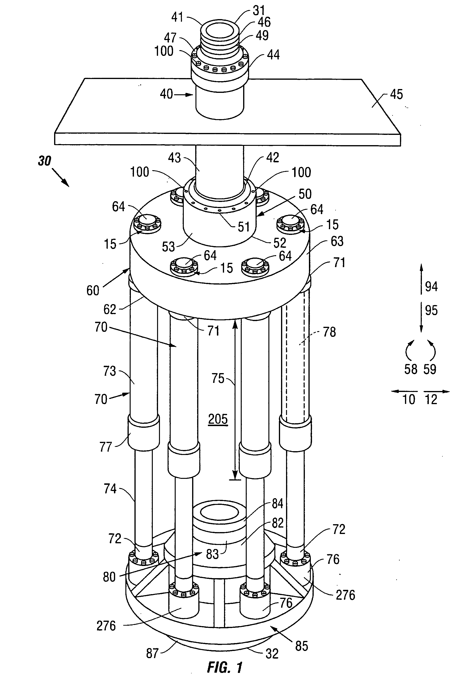
[0027] Referring now to FIGS. 1-4, broadly, the present invention is directed to tensioner 30 having first tensioner end 31, second tensioner end 32, a retracted position (as illustrated in FIG. 5), and at least one extended position (e.g., as illustrated in FIG. 3). Preferably, tensioner 30 includes the following sub-assemblies: at least one mandrel, or spool, 40 having at least one top load plate 45; at least one upper swivel assembly 50 (which may be a ball-joint, a flex-joint, or a bearing assembly, all of which are known in the art); at least one tensioning cylinder, or cylinder, 70; and at least one base 85. Base 85 facilitates connecting second end 32 of tensioner 30 to ot...


PUM


Abstract

The invention is directed to a tensioner for providing linear and angular movement of a drilling or production facility relative to a conduit or riser secured to the tensioner and to the wellhead in offshore operations. The tensioner compensates for vessel motion induced by wave action and heave and maintains a variable tension to the riser string alleviating the potential for compression and thus buckling or failure of the riser string. The tensioner of the present invention preferably includes at least one top load plate that facilitates easy and quick installation and removal of the tensioner from the rig floor of the vessel or platform. The tensioner also facilitates the placement of at least one piece of equipment disposed within the area formed by the tensioning cylinders. The tensioner may also include one or more pieces of equipment, e.g., a rotary table, integrally formed with the tensioner to further increase the ease and speed of installation and removal of the tensioner from the rig floor. Methods for installing and removing tensioners from the rig floor are also disclosed.

Description

BACKGROUND OF THE INVENTION [0001] 1. Field of the Invention [0002] The invention relates to offshore drilling and production operations and is specifically directed to drilling and production tensioners and methods for installing and removing drilling and production tensioners. [0003] 2. Description of Related Art [0004] A marine riser system is employed to provide a conduit from a floating vessel at the water surface to the blowout preventer stack or, production tree, which is connected to the wellhead at the sea floor. A tensioning system is utilized to maintain a variable tension to the riser string alleviating the potential for compression and in turn buckling or failure. [0005] Historically, conventional riser tensioner systems have consisted of both single and dual cylinder assemblies with a fixed cable sheave at one end of the cylinder and a movable cable sheave attached to the rod end of the cylinder. The assembly is then mounted in a position on the vessel to allow conveni...

Claims


Application Information

Patent Timeline
Patent Type & Authority Applications(United States)
IPC IPC(8): E21B29/12
CPCE21B19/006
Inventor WILLIAMS, RICHARD D.
Owner CONTROL FLOW
Why Eureka
Try Eureka