Power steering system

a technology of steering assist and power cylinder, which is applied in the direction of power driven steering, fluid steering, vehicle components, etc., can solve the problems of motors not working in an efficient range, the operating oil cannot be selectively distributed to the power cylinder and the reserve tank, and the steering assist is exhausted while remaining pressurized. , to achieve the effect of improving responsiveness and enhancing steering feel

Inactive Publication Date: 2006-11-16
HITACHI LTD
View PDF9 Cites 9 Cited by
  • Summary
  • Abstract
  • Description
  • Claims
  • Application Information

AI Technical Summary

Benefits of technology

[0005] It is therefore an object of the present invention to provide a power steering system which is capable of enhancing steering feel by improving responsiveness under a condition where the motor works in an efficient range.

Problems solved by technology

In the above power steering systems employing the control valve, however, the residual oil other than the required oil for steering assist is exhausted while remaining pressurized.
Therefore, this can be inefficient.
Instead, due to failing to have the control valve, it is impossible to selectively distribute the operating oil to the power cylinder and the reserve tank.
Because of this, in a case where an intrinsic or inherent discharge amount of the pump (pump discharge amount per rotation) is too large, the motor can not work in an efficient range.
This therefore results in the increase of electric power consumption.
Further, the motor may not respond sufficiently since the inertia of the motor becomes large, and thereby leads to the deterioration in steering feel.
However, if the motor works at low rpm, the efficiency of motor is reduced.
In this case as well, the electric power consumption increases due to the reduced efficiency of motor.
Furthermore, at low rpm, the response of motor is inadequate, and thereby leads to the deterioration in steering feel.

Method used


Image

  • Power steering system
  • Power steering system
  • Power steering system

Examples


Embodiment Construction

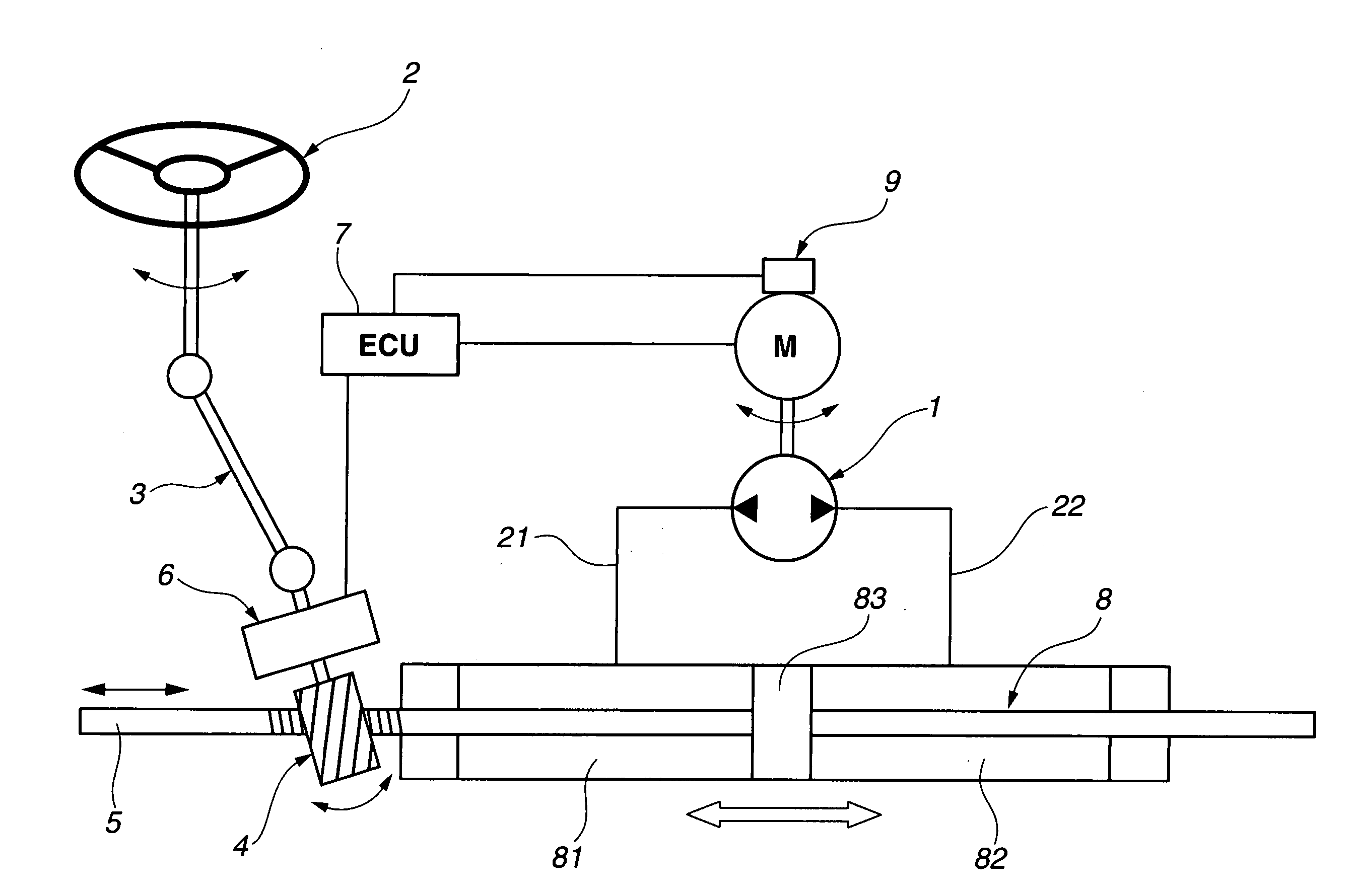
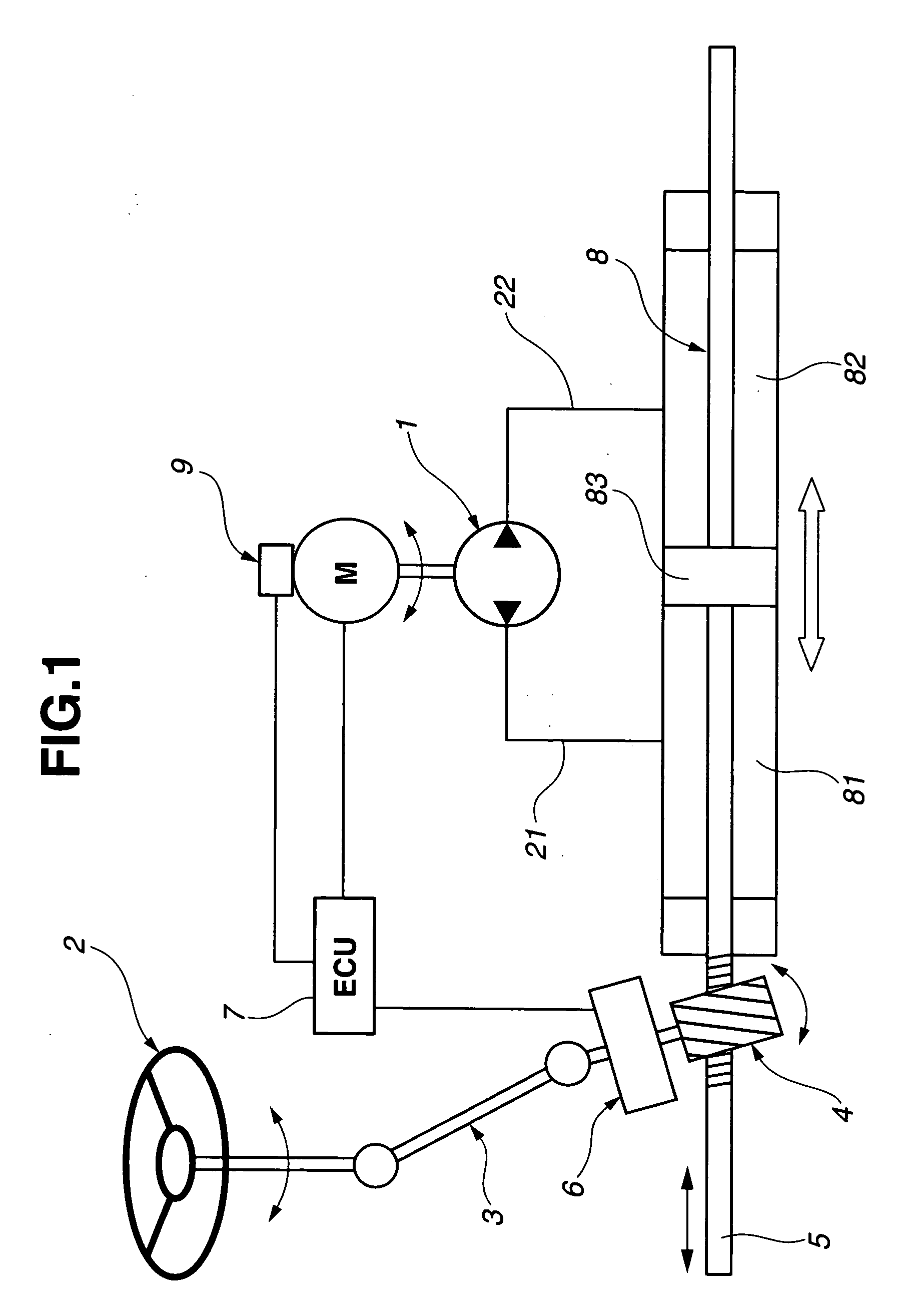
[0014] An embodiment of the present invention will be explained below with reference to the drawings. FIG. 1 shows a schematic system diagram of a power steering system. When a driver turns a steering wheel 2 (when steering wheel 2 is turned), a pinion steering gear (or a pinion shaft) 4 is driven through a steering shaft 3. And, by means of a steering mechanism (the so-called rack-and-pinion mechanism; converting rotational motion into lateral axis movement), a rack shaft 5 moves in the axial direction thereof, and thereby steers or turns front wheels (or steered road wheels, not shown). Between steering shaft 3 and pinion steering gear 4, a torque sensor 6 as a steering load detection unit is disposed so as to detect a steering effort (steering load) of steering wheel 2, and outputs a torque signal corresponding to the detected steering load to a ECU (electrical control unit) 7.

[0015] In the power steering system, a power steering mechanism is provided for assisting the movement ...


PUM


Abstract

A power steering system includes a hydraulic power cylinder having a first and a second hydraulic chambers, for assisting a steering force of a steering mechanism, a first and a second oil passages respectively connected to the first and second hydraulic chambers, a reversible pump discharging operating oil and providing oil pressure to the hydraulic power cylinder through the first and second oil passages, and a motor connected to the reversible pump and rotating the reversible pump in normal and reverse directions. A steering load detection unit detects a steering load of a steering wheel for steering of the steered road wheels, and a motor control unit outputs a control signal to the motor to bring an actual oil pressure generated by the reversible pump closer to a desired oil pressure determined based on the detected steering load. A discharge amount per rotation of the reversible pump is smaller than or equal to 5 cc.

Description

BACKGROUND OF THE INVENTION [0001] The present invention relates to a power steering system which assists steering effort. [0002] In recent years, there have been proposed and developed various power steering systems. One such power steering system has been disclosed in Japanese Patent Provisional Publication No. 2004-276664 (hereinafter is referred to as “JP2004-276664”). In JP2004-276664, the power steering system includes a power cylinder, a reversible pump connected to the power cylinder and pumping out operating oil from a reserve tank into the power cylinder, and a motor which drives or rotates the reversible pump in normal and reverse rotational directions. In addition, a piston is provided within the power cylinder, and the power cylinder and the piston cooperate to define two right and left working pressure chambers therein. Oil pressure (working fluid pressure) is selectively distributed to these right and left pressure chambers by the reversible pump which is driven by th...

Claims


Application Information

Patent Timeline
Patent Type & Authority Applications(United States)
IPC IPC(8): B62D5/06
CPCB62D5/065B62D5/064B62D5/07B62D6/10B62D5/06
Inventor SAKAKI, TOSHIMITSUKURATA, MASAKAZUTAKAHASHI, TORU
Owner HITACHI LTD
Why Eureka
Try Eureka