Apparatus and methods for conducting laser stir welding

a technology of laser stir welding and laser welding apparatus, which is applied in the field of laser stir welding, can solve the problems of not always suitable in the aerospace, automotive, marine industries, and limited production of lap-penetration joints and lap-fillet joints via laser welding, and achieves the effects of less than ideal welding conditions

Inactive Publication Date: 2006-11-16
PENN STATE RES FOUND
View PDF28 Cites 50 Cited by
  • Summary
  • Abstract
  • Description
  • Claims
  • Application Information

AI Technical Summary

Benefits of technology

[0015] A method of laser welding a pair of metal components together along a metal interface comprises providing laser radiation, passing the laser radiation through a beam conditioner, and converging the laser radiation to a focus point proximate to the metal interface. In preferred examples of the present invention, the beam conditioner comprises rotational optics, the rotational optics including one or more optical elements configured induce oscilla...

Problems solved by technology

While butt joints may be produced by laser welding, they are not always suitable in the aerospace, automotive, and marine industries.
Laser welding of lap-penetration joints and lap-fillet joints is more difficult to accomplish.
In practice, production of lap-penetration joints and lap-fillet joints via laser welding is limited.
In addition, laser welding is relatively costly.
However, with thicker materials it is progressively more diffic...

Method used


Image

  • Apparatus and methods for conducting laser stir welding
  • Apparatus and methods for conducting laser stir welding
  • Apparatus and methods for conducting laser stir welding

Examples


Embodiment Construction

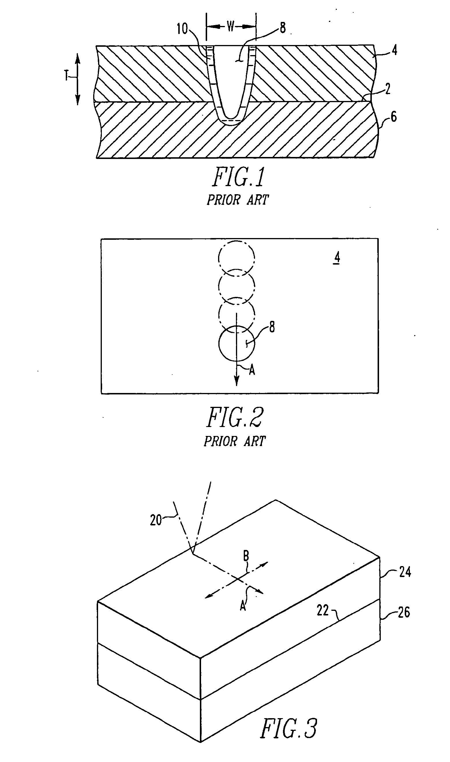
[0019] In apparatus and methods according to examples of the present invention, components (such as steel, aluminum alloys or titanium alloys) are laser welded together. A method of welding components together comprises moving a laser focus point along a first direction along an interface between the components, and oscillating the focus point through a direction different from the first direction. In a preferred embodiment, the oscillation of the focus point includes a generally circular or elliptical motion. In some embodiments of the present invention, the oscillation of the focus point is introduced using a beam conditioner including at least one rotating optical element. The oscillatory motion preferably includes a component perpendicular to the interface of the components to be welded.

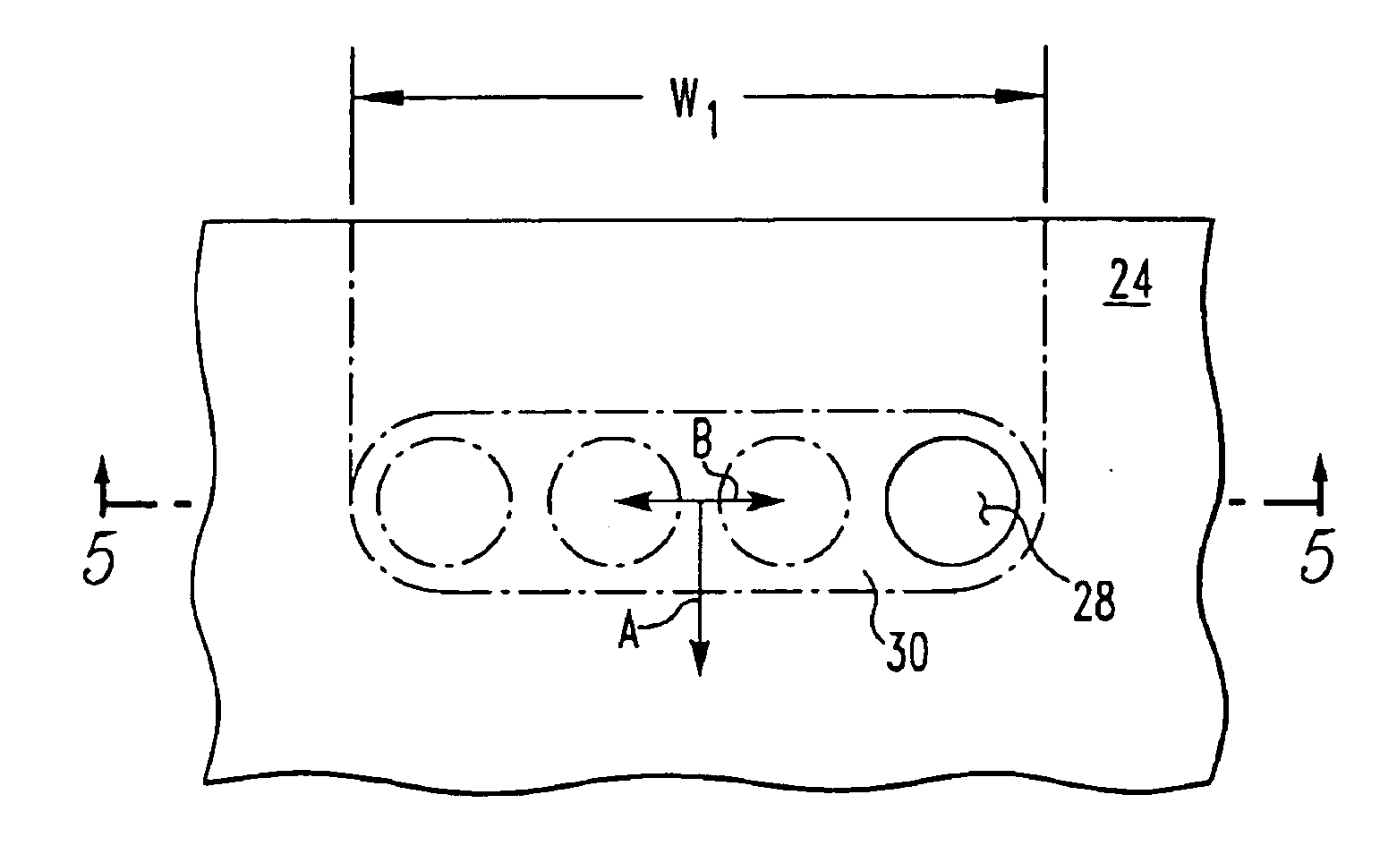
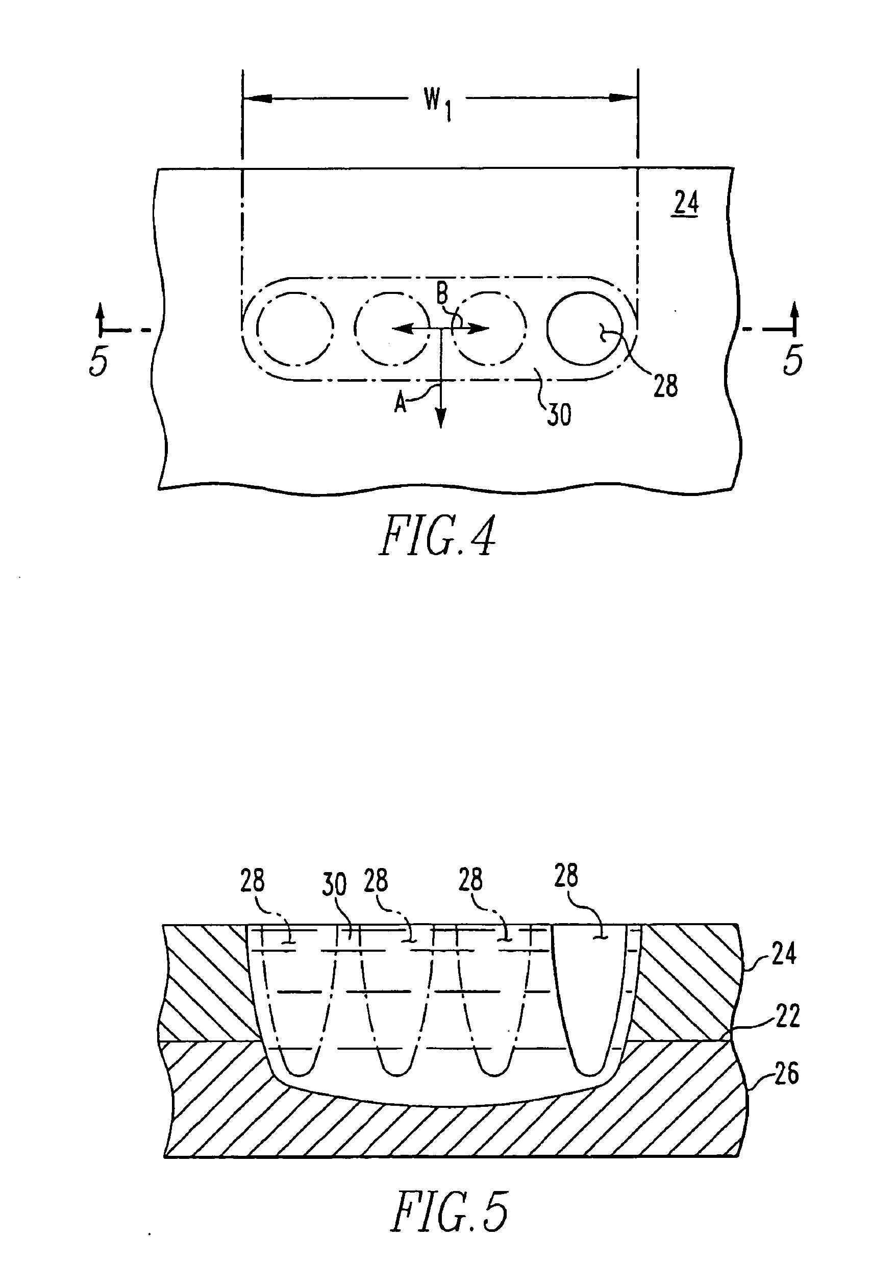
[0020]FIG. 3 shows radiation 20 (such as a laser or plasma beam) focused in a round spot (at the focus point) over an interface 22 between a pair of metal components 24 and 26. The metal compone...


PUM

PropertyMeasurementUnit
Lengthaaaaaaaaaa
Frequencyaaaaaaaaaa
Frequencyaaaaaaaaaa

Abstract

A method of welding metal components together including moving a laser beam in a first direction along an interface between a pair of metal components such that in the vicinity of the focused beam, metal from each component is vaporized to produce a keyhole in a pool of molten metal. The laser beam is oscillated in a direction different from (e.g., transverse to) the first direction such that the keyhole oscillates through the pool of molten metal and molten metal fills into the keyhole as the position of the keyhole changes. A laser welding apparatus achieves oscillation of the laser beam using optical elements in the path of the laser beam, for example trepanning optics located within an expanded portion of the laser beam.

Description

REFERENCE TO RELATED APPLICATIONS [0001] This application is a continuation-in-part of U.S. patent application Ser. No. 10 / 821,734, filed Apr. 8, 2004, which is a continuation-in-part of U.S. patent application Ser. No. 10 / 155,688, filed May 24, 2002, now U.S. Pat. No. 6,740,845, and claims priority from U.S. Prov. App. 60 / 675,607, filed Apr. 28, 2005, the contents of both of which are incorporated by reference.FIELD OF THE INVENTION [0002] The present invention relates to laser welding, and more particularly, laser welding with an oscillating laser beam. BACKGROUND OF THE INVENTION [0003] Common welded joints include butt joints, lap-penetration joints, and lap-fillet joints. Laser welding is a method of joining metal components using a focused beam of coherent light to melt adjoining components and allowing the melt to solidify into a joint. While butt joints may be produced by laser welding, they are not always suitable in the aerospace, automotive, and marine industries. Laser w...

Claims


Application Information

Patent Timeline
IPC IPC(8): B23K26/26
CPCB23K26/0639B23K26/0648B23K26/0665B23K26/0807B23K26/123B23K2203/14B23K26/203B23K26/24B23K26/26B23K2203/04B23K2203/10B23K26/1411B23K26/064B23K26/144B23K26/211B23K26/082B23K2103/04B23K2103/10B23K2103/14
Inventor MARTUKANITZ, RICHARD P.TRESSLER, JAY F.
Owner PENN STATE RES FOUND
Why Eureka
Try Eureka