
Shock isolation system for electronic devices

a technology for electronic devices and shock isolation, applied in the direction of shock absorbers, mechanical devices, low internal friction springs, etc., can solve the problems of shock and/or vibration isolation effect, and achieve the effect of limited damping characteristics

Inactive Publication Date: 2006-11-16
MITAC TECH CORP
View PDF12 Cites 17 Cited by
  • Summary
  • Abstract
  • Description
  • Claims
  • Application Information

AI Technical Summary

Benefits of technology

[0008] Hence the primary object of the invention is to provide a shock and / or vibration isolation system for electronic devices that can buffer instantaneous acceleration and dissipate kinetic energy through damping characteristics, to prevent damages that might occur to electronic devices, caused by the secondary impact generated by the compressed helical springs.
[0009] Another object of the invention is to provide a shock and / or vibration isolation system for electronic devices that provides a second level shock and / or vibration isolation protection to prevent excessive instantaneous acceleration and vibration amplitude, and enable the shock and / or vibration isolation apparatus to function normally.
[0011] By means of the construction set forth above, when the first baseboard receives shock and / or vibrations generated by a vibration source, the helical springs deform elastically to transform the shock and / or vibrations to elastic potential energy to protect the second baseboard and the electronic device against the direct impact of the shock and / or vibrations. The damping elements dissipate kinetic energy while the helical springs deform thereby, to further absorb the shock and / or vibrations and prevent the helical springs from generating excessive high speed and acceleration during initial restoration, thus can avoid the secondary impact on the second baseboard.

Problems solved by technology

The shock and / or vibration isolation effect suffers.

Method used


Image

  • Shock isolation system for electronic devices
  • Shock isolation system for electronic devices
  • Shock isolation system for electronic devices

Examples


Embodiment Construction

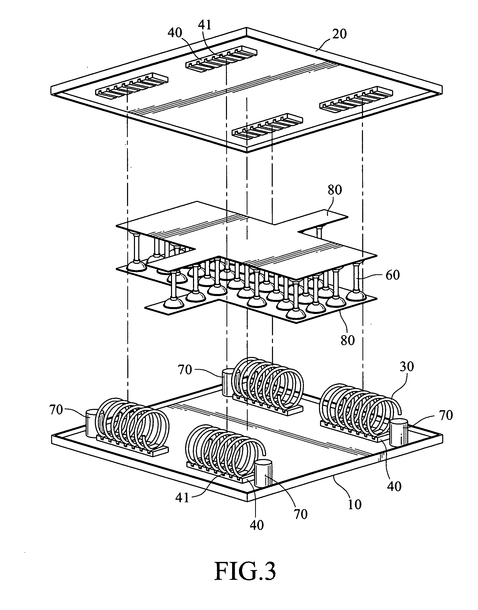
[0022] Refer to FIGS. 3 and 4 for an embodiment of the shock isolation system for electronic devices of the invention. It aims to hold an electronic device, which is sensitive to shock and / or vibration, such as a notebook computer, and isolate the electronic device from a vibration source. By providing an improved elastic and damping effect, impact on, or excessive displacement vibration of the electronic device can be prevented so that damage of electronic elements in the electronic device or breaking of contacts between the elements can be avoided.

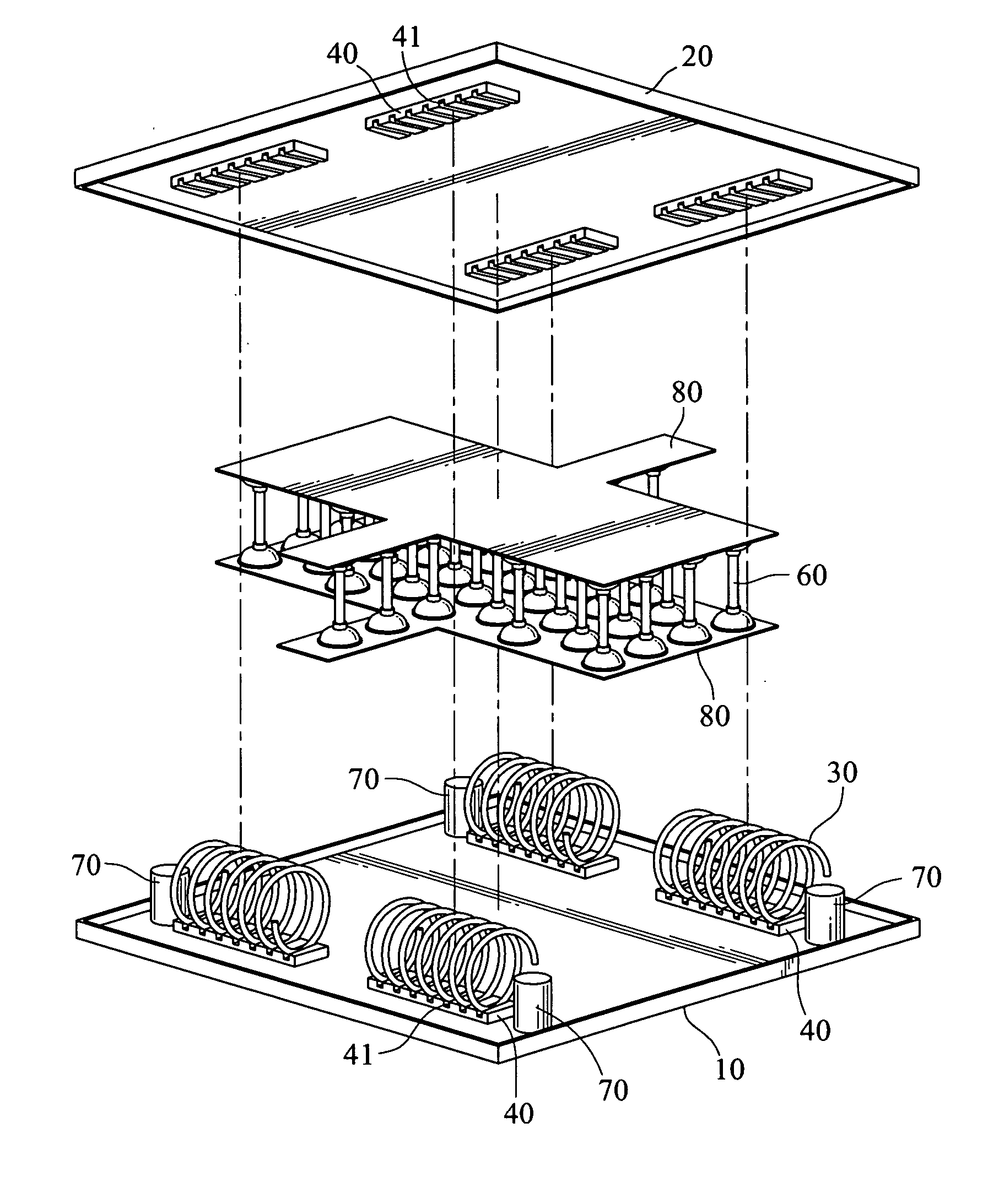
[0023] The shock isolation system for electronic devices according to the invention includes a first baseboard 10, a second baseboard 20, a plurality of helical springs 30, and a plurality of holding elements 40.

[0024] The first baseboard 10 is a rectangular plate mounted onto a vibration source, such as a motor vehicle, ship or a platform of large machinery to receive a shock and / or vibration impact generated by the vibration source. ...


PUM

PropertyMeasurementUnit
distanceaaaaaaaaaa
diameteraaaaaaaaaa
stressaaaaaaaaaa

Abstract

A shock isolation system for electronic devices includes a first baseboard, a second baseboard and a plurality of helical springs interposed transversely between the first baseboard and the second baseboard. The helical springs can deform horizontally and vertically to isolate horizontal and vertical vibration-impact on the electronic devices. The first baseboard and the second baseboard further are bridged by a plurality of damping elements, which have damping characteristics to dissipate kinetic energy and reduce the vibration amplitude and instantaneous acceleration between the first baseboard and the second baseboard, thereby to enhancing the composite effect. The first baseboard further has a plurality of buffer struts to separate the first baseboard and the second baseboard, and prevent the second baseboard from directly hitting the first baseboard.

Description

BACKGROUND OF THE INVENTION [0001] 1. Field of Invention [0002] The present invention relates to shock and / or vibration isolation and protection of electronic devices and particularly to a shock and / or vibration isolation system for an electronic device mounting onto an automotive vehicle. [0003] 2. Related Art [0004] Notebook computers used in industry or military often have to be operated in a harsh environment. For instance, for a notebook computer located on industrial machinery, because the machinery generates mechanical shock and / or vibration during operation, operation of the hard disk in the computer is affected. Other elements also constantly receive stress due to acceleration. As a result, disconnection might happen or the elements could be damaged. The notebook computers used in military encounters even worse conditions. They often have to be operated on automotive vehicles. The road condition could be rough and vibration could occur constantly. The vibration amplitude an...

Claims


Application Information

Patent Timeline
Patent Type & Authority Applications(United States)
IPC IPC(8): F16F1/36
CPCF16F1/065F16F1/373F16F2236/025F16F13/005F16F3/10
Inventor LEE, GWO-SHIANGCHEN, WEI-CHINKANG, CHUANG-CHINGHO, CHING-FANG
Owner MITAC TECH CORP
Learn More