Splicing Device and Method for Sealing Conduit Spaces

a splicing device and conduit technology, applied in the direction of pipe joints, fluid pressure sealed joints, sleeve/socket joints, etc., can solve the problems of reducing the likelihood of damage to these important utilities, and unfavorable installation and maintenan

Inactive Publication Date: 2006-11-16
MINEMYER JOHN T +3
View PDF57 Cites 16 Cited by
  • Summary
  • Abstract
  • Description
  • Claims
  • Application Information

AI Technical Summary

Benefits of technology

[0010] It is an object of the present invention to provide a new and us

Problems solved by technology

The elimination of such poles provide a more aesthetically pleasing environment since the distraction of the poles and wiring extending therebetween can create an unsightly appearance in a neighborhood.
Moreover, the placing of electrical and telecommunication cables underground reduces the likelihood of damage to these important utilities.
Where telephone or electric poles are used, strong winds can break the poles which in turn can break the wiring.
This not only interrupts the utility service but also poses a threat where electrical power lines become severed.
Placing electrical and telecommunications underground, however, is not without its difficulties.
Placing these cables underground exposes them to a greater threat of mold, mildew and water damage.
If no seal is achieved, it becomes difficult to introduce the fiber optic cable through the conduit since a leak will cause a pressure drop in the force provided to drag the cable through the conduit.
Moreove

Method used


Image

  • Splicing Device and Method for Sealing Conduit Spaces
  • Splicing Device and Method for Sealing Conduit Spaces
  • Splicing Device and Method for Sealing Conduit Spaces

Examples


Embodiment Construction

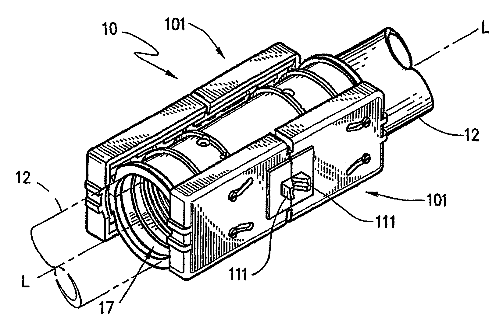
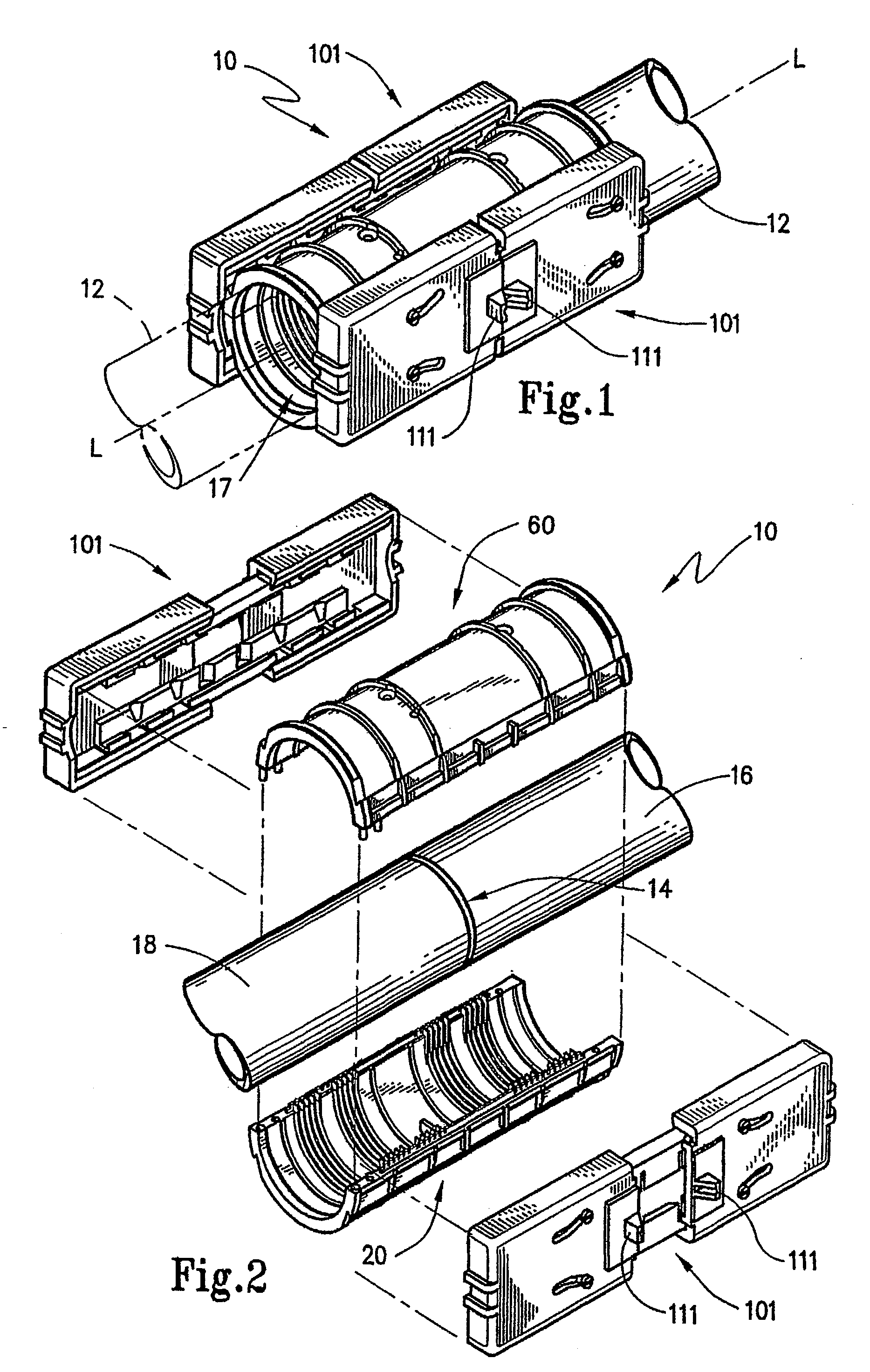
[0052] The present invention is directed to a splicing device that is adapted to mount around a portion of conduit of pre-determined size and cross-sectional geometry. The splicing device is operative to seal a space in such conduit so that the conduit is isolated from external contaminates and, in addition, is substantially airtight. Normally, this space is defined by the junction interface of two separate pieces of conduit in a continuation conduit line. However, it should be understood that the splicing device of the present invention could also be used to seal around a rupture or a break in the conduit. Thus, for purposes of this invention, the term “space” includes the above-described situations and other gaps, ruptures or other spaces that might occur on a conduit line.

[0053] Accordingly, as is introduced in FIG. 1, splicing device 10 is shown mounted around a portion of conduit 12 that is a pre-determined size and cross-sectional geometry. In FIG. 1, conduit 12 is in the for...


PUM


Abstract

A splicing device (10) is provided for sealing a conduit space (14) between two pipe sections (16,18). The splicing device includes a first body (20) and a second body (60) that are formed as an integral one-piece. A pair of clasp members (101) are mounted on the first and second body sections to secure them in an assembled state. To allow for mechanical advantage in closing the clasp members, each member is provided with an outwardly oriented ear (111) that can be engaged to a tool to force the members towards one another.

Description

FIELD OF THE INVENTION [0001] The present invention broadly concerns sealing spaces in conduit. The invention more specifically concerns sealing the abutting ends of two sections of conduit in an airtight manner. This invention particularly is directed to a device which mounts on the external surface of innerduct in order to connect two sections of innerduct together in an air tight manner. BACKGROUND OF THE INVENTION [0002] The use of conduits and ducts has been wide-spread for a substantial period of history. The use of networks of piping dates back at least to Roman Empire times wherein lead pipes were used to convey water for domestic use. Conduits, ducts and the like have been used to carry a variety of fluids, both liquid and gaseous in industry environments. Indeed, conduits are sometimes used to convey particulate matter from one location to another. [0003] In addition to their ability to convey materials, conduits have been used to provide a protected environment in other m...

Claims


Application Information

Patent Timeline
IPC IPC(8): F16L17/00F16L19/00F16L21/02F16L21/06
CPCF16L21/08F16L21/06
Inventor MINEMYER, JOHN T.SMITH, HERBERT V.PAYNE, GREGORY T.DIMAMBRO, VICTORIA
Owner MINEMYER JOHN T
Why Eureka
Try Eureka