Injection mold design system and injection mold design method

a mold design and injection mold technology, applied in the field of injection mold design system and injection mold design method, can solve the problems of lack of knowledge and experience in mold design

Inactive Publication Date: 2002-09-12
FUJITSU LTD
View PDF7 Cites 13 Cited by
  • Summary
  • Abstract
  • Description
  • Claims
  • Application Information

AI Technical Summary

Benefits of technology

[0015] It is an object of the present invention to provide a design system capable of designing an injection mold readily and in short time and a design method employed in the same.
[0017] According to the injection mold design method of the present invention, design items can be reduced by preparing parameters of the mold parts and fixing parts as patternized information, and in addition correction, change, etc. of the product shape and the mold profile can be effected automatically. Consequently, man-hour of design in typical design operations can be significantly reduced.
[0019] With the above, the present invention may extremely contribute to the mold design support system capable of executing correction of the product shape, design of the mold, and design of manufacturing jigs in an interactive manner.

Problems solved by technology

In addition, lack of knowledge and experience as to the mold design can be made up for by utilizing a loop check function for the split borderlines and a nest split function.

Method used


Image

  • Injection mold design system and injection mold design method
  • Injection mold design system and injection mold design method
  • Injection mold design system and injection mold design method

Examples


second embodiment

[0209] (2) Second Embodiment

[0210] FIG. 12 is a flowchart illustrating detection process of draft-sloped planes according to the second embodiment of the present invention. In this process, planes to which draft slope should be provided may be extracted from the product shape in the draft-sloped plane providing section 42.

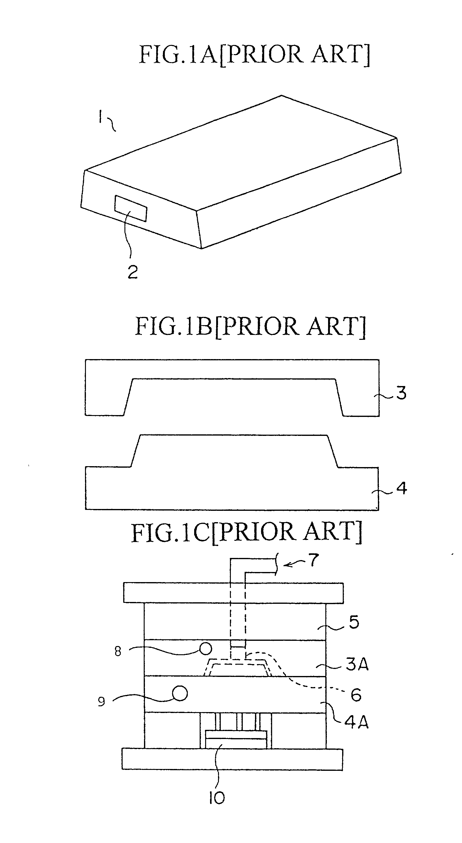
[0211] First, in step C1, the product shape data D1 may be read from the design data memory 11. In step C2, plane elements of the product shape are read out. The plane elements may correspond to bottom plane, side plane, plane of rising portion of the product 1.

[0212] Then, in step C3, the designer may discriminate kinds of the plane elements. If a plane to be inspected has been a flat surface, the process proceeds to step C4 where center of gravity of the plane is calculated. The process then advances to step C7.

[0213] If the plane to be inspected has been a free-form surface, then the process moves to step C5 where the designer may input the number of grid or the...

third embodiment

[0224] (3) Third Embodiment

[0225] FIG. 13 is a flowchart illustrating assign process of priority levels to draft slopes according to the third embodiment of the present invention. In this process, priority levels may be assigned to respective sloped planes detected in the second embodiment in the draft-sloped plane providing section 42.

[0226] In FIG. 13, in step D1, information of sloped plane previously registered may be first read from the work memory 13. In step D2, a magnification center of the draft slope plane may then be calculated. The magnification center is a center of gravity of the product when the product shape is projected onto the flat plane being parallel to the mold opening direction.

[0227] Subsequently, in step D3, the inspection vector k may be calculated before the magnification being effected. In step D4, the product shape may be magnified in the direction perpendicular to the mold opening direction Z on the display 19. FIG. 14 is an isometric drawing showing th...

fourth embodiment

[0234] (4) Fourth Embodiment

[0235] FIG. 16 is a flowchart illustrating provision process of draft slope according to the fourth embodiment of the present invention. In this process, slant may be given to the draft-sloped plane by the draft-sloped plane providing section 42. As the method for providing the slant, a method for simply inclining the sloped plane, a method for utilizing a slant plane of circular cone, and a method for forming a ruled plane which being formed by connecting a shifted base side edge of the rising plane and a leading edge of the same by shifting the base side edge at a distance in the horizontal direction may be listed.

[0236] In FIG. 16, in step E1, element data D3 of edge in the product shape previously recorded are first read out from the work memory 13.

[0237] Then in step E2, the designer may select a sloped plane. If the selected plane is a flat plane, the process advances to step E3 where, as shown in a broken line circle in FIG. 17, the sectional view ...


PUM

PropertyMeasurementUnit
depthaaaaaaaaaa
distanceaaaaaaaaaa
distanceaaaaaaaaaa

Abstract

An injection mold design method for correcting a profile of a product to be fabricated into a releasable profile from a mold to design an injection mold based on a corrected product shape, utilizing a storage device for storing information of the product shape and mold profile, a display device for displaying the product shape or the mold profile on a screen based on the information read from the storage device, an input device for inputting designation information necessary for correction of the product shape or the mold profile, and a controlling device for unloading information of lines or planes being obstructive to correction of the product shape and the mold profile in the storage device in response to the designation information input by the input device. The method comprises removing lines or planes from the screen, and replotting the lines or the planes on the screen in terms of the information of lines or planes unloaded into the storage device after the correction operation of the product shape or the mold profile is completed.

Description

BACKGROUND OF THE INVENTION[0001] 1. Field of the Invention[0002] The present invention relates to an injection mold design system and an injection mold design method and, more particularly, a design support system for a mold used for fabricating resin (plastics) injecting moldings and a design method for designing the mold.[0003] 2. Description of the Related Art[0004] In recent years, according to demands for more variety of product design, users' various usages etc., plastics have been widely used as material of enclosures for electrical products since they may present an attractive appearance and may be molded arbitrarily. In addition, it entails such advantages that reduction in the number of parts and simplification of assembly may be attained. This is because seats, bosses (projections), etc., these being used for mounting printed circuit boards and other parts, and reinforcing members such as ribs may be formed integrally with the enclosures if the enclosures are fabricated ...

Claims


Application Information

Patent Timeline
Patent Type & Authority Applications(United States)
IPC IPC(8): G06F17/50B29C45/26B29C45/76G05B19/4099
CPCG05B2219/35044G05B2219/35078B29C33/3835B29C45/26G05B19/4099Y02P90/265Y02P90/02
Inventor NISHIYAMA, SHUSAKUYAMAGUCHI, SHINGOKIMURA, TATSUOIMAKADO, MASAYUKIASANO, NAOKIMAKIUCHI, FUMIHIKO
Owner FUJITSU LTD
Why Eureka
Try Eureka