Pallet jack antenna for RFID system

a technology of rfid and pallet jack, which is applied in the field of antenna systems, can solve the problems of rarely synchronized, extraneous data, and inability to fully take into account the above mentioned aspects in the initial attempts to effectively implement rfid technology in the warehouse environment, and achieve the effect of accurate reading of rfid tags

Active Publication Date: 2006-11-16
EMS TECHNOLOGIES
View PDF29 Cites 49 Cited by
  • Summary
  • Abstract
  • Description
  • Claims
  • Application Information

AI Technical Summary

Benefits of technology

[0020] The fork-mounted antenna may incorporate any of several designs that allows for transmission of upward-looking RFID signals. The designs can be accommodated within standard pallet jack fork dimensions and can be incorporated as OEM design or retrofit. In the present invention, the antenna's structure and location on the pallet jack forks permit use of focused low-level RF power, which helps to ensure accurate reading of RFID tags on the pallets being loaded without reading unintended nearby tags. Multiple antennas may be mounted on a single fork to provide required coverage for double-length fork.

Problems solved by technology

Prior attempts to effectively implement RFID technology in a warehouse environment have typically failed to fully take into account the aspects mentioned above.
However, this is seldom synchronized with lift operator instructions and application instructions to the operator.
RFID systems can, and typically do, read multiple tags; but this often results in extraneous data, which fails to deliver discrete, precise data as required by the application.
Thus, the use of RFID systems in warehouse inventory control presents a unique set of problems that have to be resolved to ensure efficient operation of the RFID system.
For example, in some instances, a limited signal strength is required to prevent reading of undesired adjacent RFID tags.
When RFID tags are improperly aligned or partially obscured, an interrogating antenna may not be able to read the RFID tag.

Method used


Image

  • Pallet jack antenna for RFID system
  • Pallet jack antenna for RFID system
  • Pallet jack antenna for RFID system

Examples


Embodiment Construction

[0039] Reference will now be made in detail to the particular embodiments of the present invention, examples of which are illustrated in the accompanying drawings.

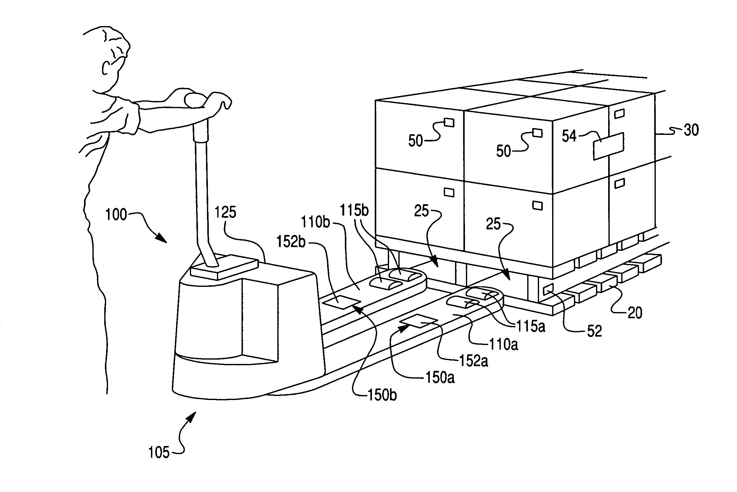
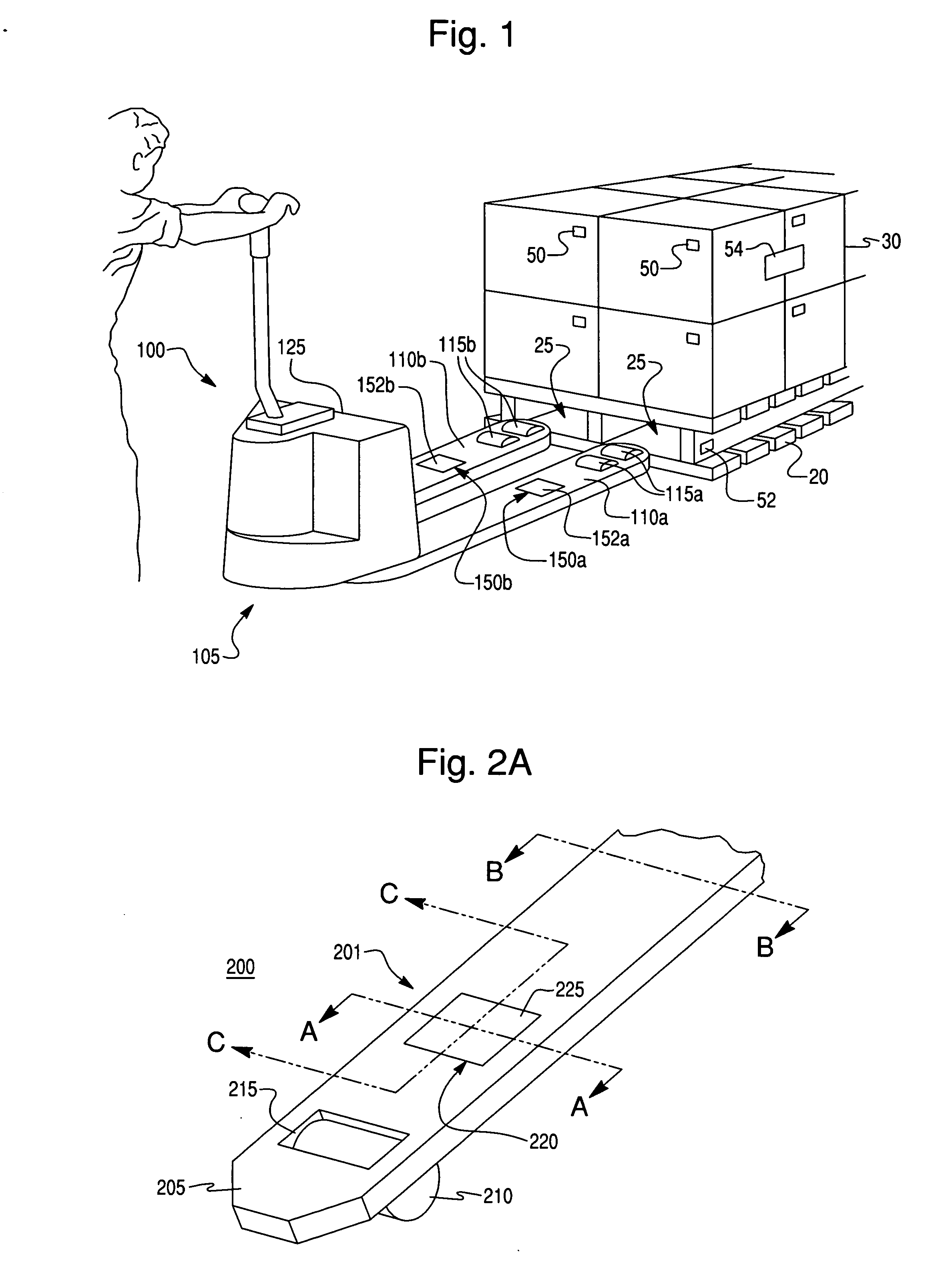
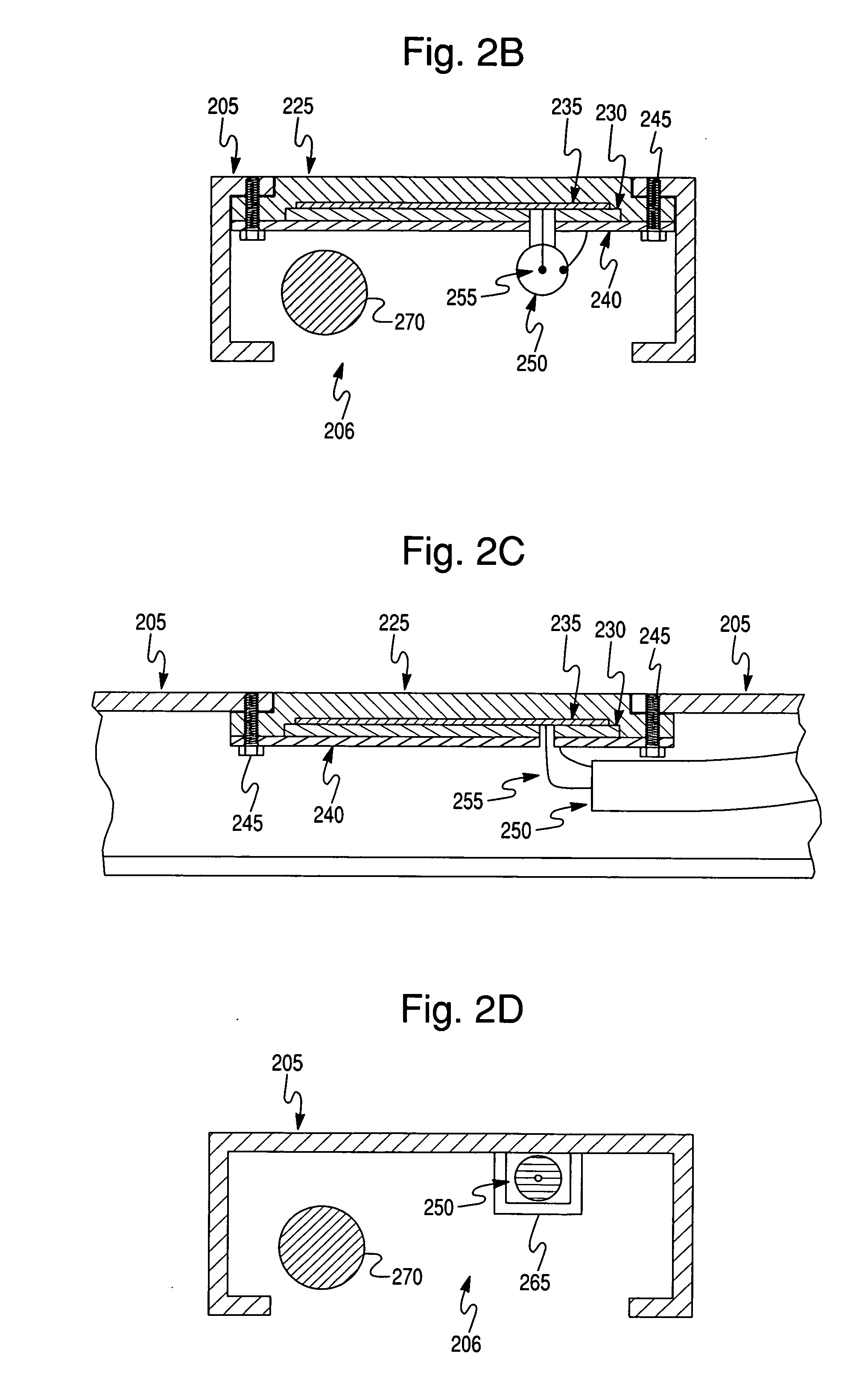
[0040]FIG. 1 provides a perspective view of a pallet jack 100, suitable for use with embodiments of the present invention. The pallet jack 100 shown is a motorized hand pallet jack. However, numerous other types of pallet jacks are contemplated with embodiments of the present invention. For example, a manual hand pallet jack, pallet truck, rider pallet truck, or platform truck may also be used. The pallet jack 100 includes a pair of forks 110a, 110b that are affixed at one end to the carriage area 105. The other end of forks 110a, 110b are supported by front wheels 115a, 115b, respectively. The front wheels 115a, 115b, are mounted inside the end of the forks 110a, 110b and extend to the floor. The forks 110a, 110b typically slide under a pallet 20 that holds inventory 30. More particularly, the pallet jack slides into pal...


PUM


Abstract

The present invention provides an antenna for reading RFID tags in a material handling environment. At least one ruggedized, upward-looking antenna is mounted on the fork (or other base-level platform) of a pallet jack or pallet truck. The antenna can be configured to read RFID tags on pallets that are loaded on the pallet jack and communicate the tag information to a warehouse management system.

Description

CROSS REFERENCE TO RELATED APPLICATIONS [0001] This application claims priority under 35 U.S.C. § 119(e) from U.S. Provisional Patent Application Nos. 60 / 680,925, filed on May 13, 2005, and 60 / 718,947, filed on Sep. 20, 2005, both of which are incorporated herein by reference.STATEMENT REGARDING SPONSORED RESEARCH OR DEVELOPMENT [0002] Not Applicable. REFERENCE TO SEQUENCE LISTING [0003] Not Applicable. BACKGROUND OF THE INVENTION [0004] 1. Field of the Invention [0005] This invention relates generally to antenna systems, and more particularly to mobile wireless data collection systems. [0006] 2. Description of Related Art [0007] Current “best practices” employed in the movement and tracking of goods in warehouses and distribution centers include the use of barcode-based data collection and wireless networked computers on lift trucks and other mobile material handling equipment. While these technologies have greatly enhanced the efficiency and accuracy of warehousing operations over...

Claims


Application Information

Patent Timeline
Patent Type & Authority Applications(United States)
IPC IPC(8): G08B13/14
CPCB62B3/06B62B5/0096B66F9/0755B66F9/12G06K7/0008G06K7/10079H01Q13/22G06K2017/0051G06Q10/087H01Q1/22H01Q1/2216H01Q9/0421G06K7/10336
Inventor ROEDER, WILLIAM H.RUNYON, DONALD L.SORENSON, RICHARD W. JR.CLOTT, MICHAEL SAYRE
Owner EMS TECHNOLOGIES
Why Eureka
Try Eureka