Optical system for variable direction of view instrument

a viewing instrument and optical system technology, applied in the field of objective optical systems for viewing instruments, can solve the problems of insufficient chromatic and geometric correction, insufficient telecentricity, insufficient telecentricity, etc., and achieve the effect of large scanning range and field of view

Active Publication Date: 2006-11-16
KARL STORZ IMAGING INC
View PDF17 Cites 23 Cited by
  • Summary
  • Abstract
  • Description
  • Claims
  • Application Information

AI Technical Summary

Benefits of technology

[0014] Accordingly, it is an object of the present invention to provide an optical system for a variable direction of view instrument that provides a large scanning range and field of view.

Problems solved by technology

However, all of these disclosures pertain to objective systems for endoscopes that have fixed viewing directions, and are not appropriate with endoscopes having a variable direction of view.
Even though this design is optimally compact, the use of only the rotating and fixed prisms 10, 12 results in an unacceptably small field of the view and is not telecentric.
While this design provides an improved field of view, it is still not telecentric, does not provide sufficient chromatic and geometric correction, and is not optimally compact, as evidenced by the increased size of the pivotable prism 10.
Additionally, the increased prism size also causes the scanning range to be limited, as the rotating prism 10 would be obstructed by the lens group 30.
Therefore, a continuous challenge presented by these systems is producing a suitable objective optical system that adequately accommodates this sort of dual reflector design.
To date, this has been difficult to accomplish, as these interests often conflict.
For example, decreasing the size of the optical elements typically reduces the amount of light admitted by the system and adversely affects the image brightness.
As another example, increasing the field of view typically exacerbates optical aberrations and degrades image quality.
This is not ideal, as this location of the aperture stop negatively affects both system size and performance—the system should be designed to accommodate larger diameter light flow on either side of it.

Method used


Image

  • Optical system for variable direction of view instrument
  • Optical system for variable direction of view instrument
  • Optical system for variable direction of view instrument

Examples


Embodiment Construction

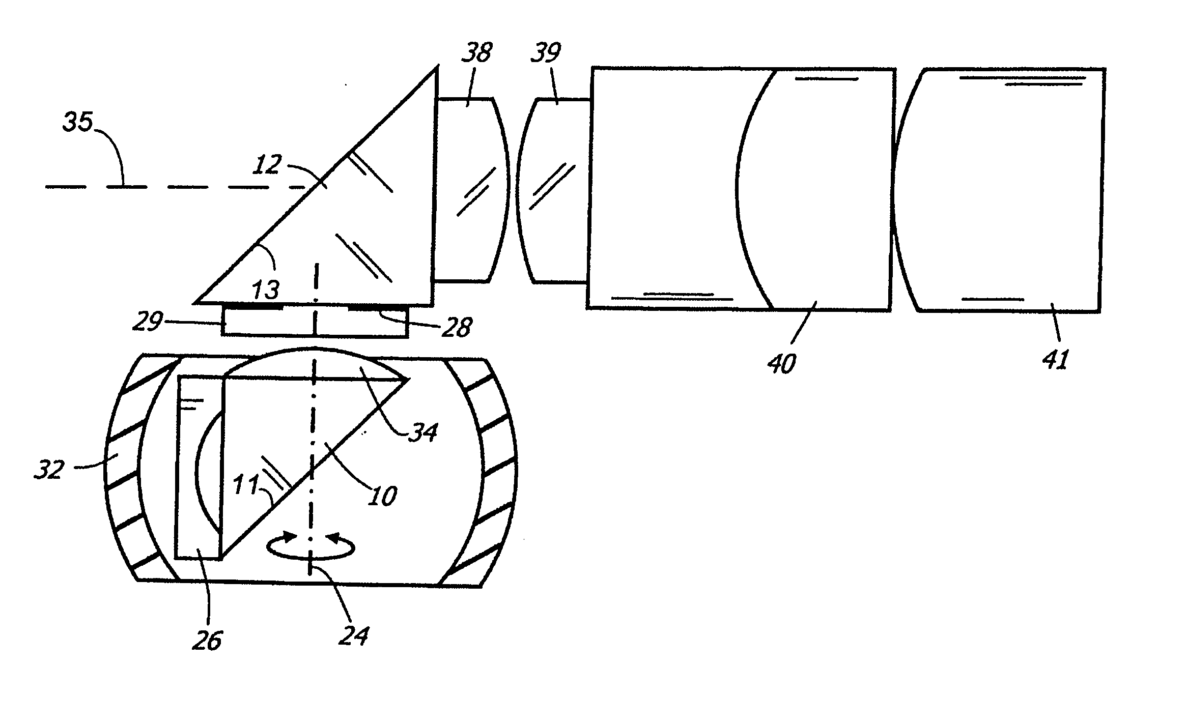
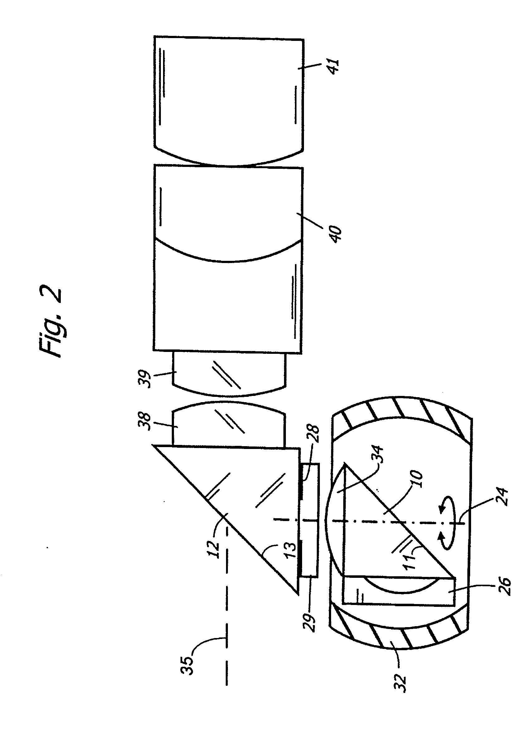
[0036] The basic components of one embodiment of a optical system for a variable direction of view instrument in accordance with the invention are illustrated in FIGS. 2-3. As used in the description, the terms “top,”“bottom,”“above,”“below,”“over,”“under,”“above,”“beneath,”“on top,”“underneath,”“up,”“down,”“upper,”“lower,”“front,”“rear,”“back,”“forward” and “backward” refer to the objects referenced when in the orientation illustrated in the drawings, which orientation is not necessary for achieving the objects of the invention.

[0037] Referring to FIG. 2, and starting from the object side, this optical system comprises a spherical viewing window 32 with zero optical power (or as close to zero as current optical fabrication techniques will allow), a first lens 26 of negative refraction power, a first reflector 10, a second lens 34 of positive refractive power, an aperture stop 28 seated on the back of a mounting element 29 (which could be constructed with a weak positive optical po...


PUM


Abstract

A optical system for a viewing instrument with a variable direction of view is disclosed generally comprising shaft, first and second reflectors located at the distal end of the shaft, where the first reflector rotates about an axis angularly offset from the longitudinal axis of the shaft, and an entrance pupil positioned in the optical path created by the reflectors and preceding the reflecting surface of the second reflector. In certain embodiments, the entrance pupil comprises an aperture stop positioned between the first and second reflectors. In some embodiments, the system includes negative and positive lenses located adjacent the entrance and exit faces of the first reflector.

Description

CROSS-REFERENCE TO RELATED APPLICATIONS [0001] This patent application claims the benefit of, under Title 35, United States Code, Section 119(e), U.S. Provisional Patent Application No. 60 / 648,332, filed Jan. 28, 2005.FIELD OF THE INVENTION [0002] The present invention relates to an apparatus for obtaining wide angles of view in small areas, such as a surgical site in a patient's body. More specifically, the invention relates to an objective optical system for a viewing instrument, such as an endoscope, with a variable direction of view. BACKGROUND OF THE INVENTION [0003] Viewing instruments, such as endoscopes, are generally well known in the art. Generally, an endoscope is a medical device for insertion into a body passageway or cavity that enables an operator to view and / or perform certain surgical procedures at a site inside a patient's body. As is known, endoscopes may be either rigid or flexible, and generally include a long tubular member equipped with, for example, some type...

Claims


Application Information

Patent Timeline
Patent Type & Authority Applications(United States)
IPC IPC(8): G02B17/00
CPCA61B1/00183A61B1/00096G02B23/243G02B13/22
Inventor TESAR, JOHN C.HALE, ERIC L.SCHARA, NATHAN JONHOEG, HANS DAVID
Owner KARL STORZ IMAGING INC
Why Eureka
Try Eureka