Turbulator on the underside of a turbine blade tip turn and related method

a turbine blade and turbine blade technology, applied in the field of cooling of turbine blades, can solve the problems of increasing the pressure loss associated with plural ribs, and achieve the effects of reducing the risk associated, facilitating heat transfer, and minimizing additional pressure loss

Inactive Publication Date: 2006-11-16
GENERAL ELECTRIC CO
View PDF5 Cites 9 Cited by
  • Summary
  • Abstract
  • Description
  • Claims
  • Application Information

AI Technical Summary

Benefits of technology

[0004] This invention provides enhanced heat transfer in the tip region of a closed-loop, steam-cooled turbine blade to reduce the risk associated with a loss of thermal barrier coating and, at the same time, minimizes additional pressure loss resulting from the addition of the turbulence-enhancing feature. In accordance with an exemplary embodiment, a single turbulator or heat transfer enhancement device is provided on the underside of the tip cap, adjacent the coolant flow tip turns at the radially outer end of the blade. This arrangement provides improved thermal protection in the event of thermal barrier coating failure and minimal pressure loss through the turn.

Problems solved by technology

The disadvantage to the use of multiple features, however, is increased pressure loss associated with plural ribs.

Method used


Image

  • Turbulator on the underside of a turbine blade tip turn and related method
  • Turbulator on the underside of a turbine blade tip turn and related method
  • Turbulator on the underside of a turbine blade tip turn and related method

Examples


Embodiment Construction

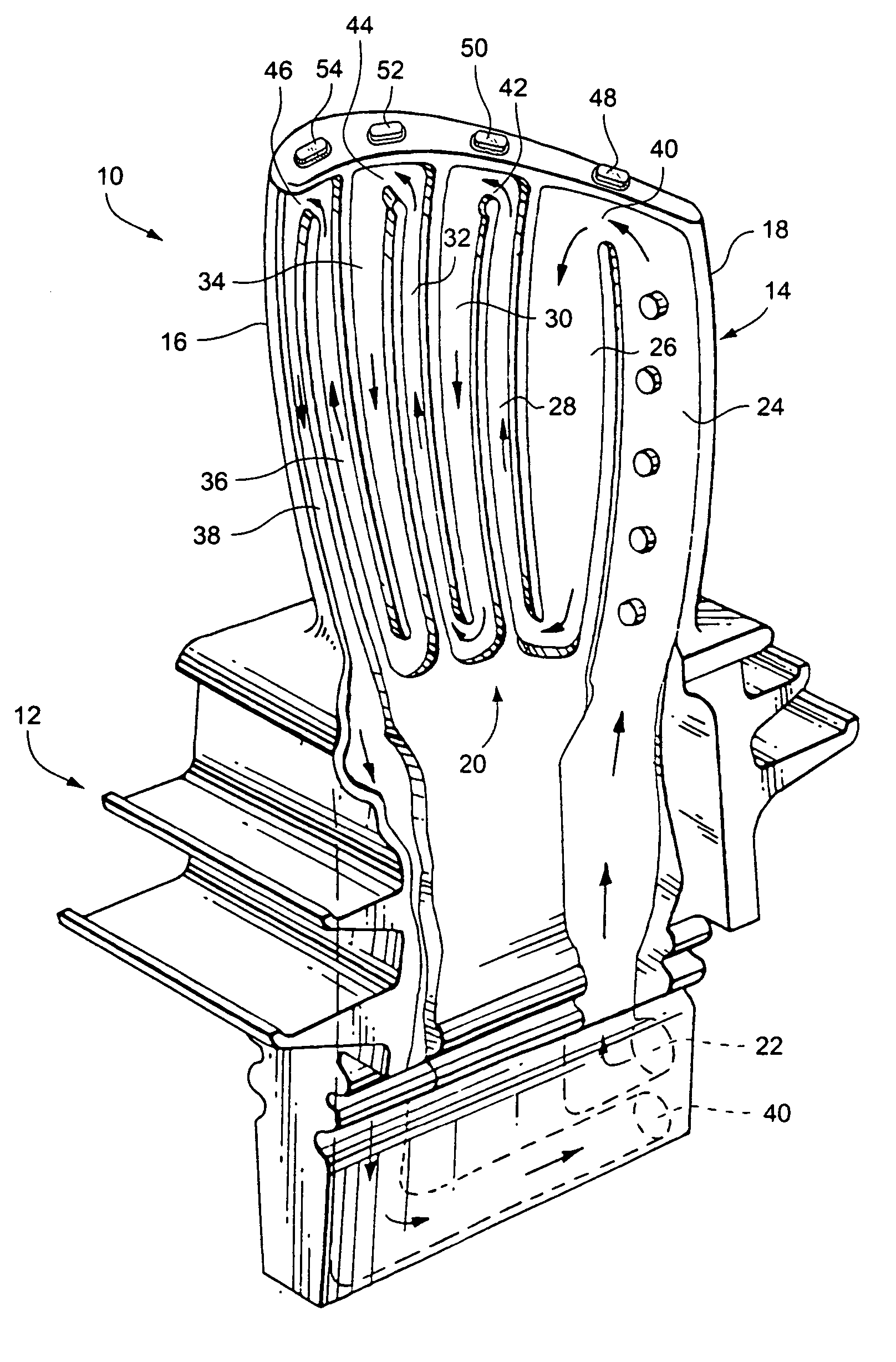
[0014] With reference to FIG. 1, there is shown in simplified form a turbine blade 10 having shank portion 12 and an airfoil portion 14. The airfoil portion 14 is formed with respective leading and trailing edges 16, 18. A closed-loop, serpentine cooling circuit 20 is formed within the airfoil portion. Cooling steam entering the blade 10 via inlet 22 flows through the single closed serpentine circuit 18 having a total of, for example, eight radially extending passages 24, 26, 28, 30, 32, 34, 36 and 38 connected alternately by 180° return U-bends 40, 42, 44 and 46. Inlet 20 thus communicates with the first radial outflow passage 22, and the last radial inflow passage 38 communicates with outlet 40. The total number of radial passages may vary in accordance with the specific design criteria. The cooling steam could also enter the blade via 40 and flow in the opposite direction to the arrows shown, exiting at 22. In addition, the invention is not restricted to a single serpentine circu...


PUM


Abstract

A turbine blade includes a shank portion and an airfoil portion with leading and trailing edges and a radially outer tip. An internal closed-loop cooling circuit is formed within the airfoil portion and includes at least one radial outflow passage and at least one radial inflow passage connected by at least one respective tip turn at the radially outer end of the airfoil portion. At least one tip turn is provided with a single turbulence-enhancement device on an underside of the radially outer tip, projecting into the tip turn.

Description

BACKGROUND OF THE INVENTION [0001] This invention relates generally to the cooling of turbine blades and, more specifically, to a turbulence-enhancing mechanism on the underside of a tip turn of a cooling passage in a closed-circuit steam-cooled turbine blade. [0002] In a closed-circuit steam-cooled turbine blade, effective cooling of the radially outer tip region is critical for the life of the part. Unlike a typical air-cooled turbine blade where the coolant can be erected through holes in the blade to provide a relatively cool film over the surface to protect the part, all of the cooling capacity in a steam-cooled turbine blade must come from inside the machine. Heat transfer enhancement, relative to that of a flat plate or pipe configuration, occurs at the tip turns due to the turning of the flow in the serpentine circuit, and is typically sufficient to cool the tip region of the blade under normal operating conditions. However, in the event of a failure in the thermal barrier c...

Claims


Application Information

Patent Timeline
Patent Type & Authority Applications(United States)
IPC IPC(8): F01D5/18B63H1/14F02C7/18F15D1/02
CPCF01D5/187F05D2250/185Y02T50/67F05D2260/2214F05D2260/2212F05D2260/22141Y02T50/676Y02T50/60
Inventor EASTMAN, JOHN ALANFINDLAY, MATTHEW JAMESEBACHER, JON ALLEN
Owner GENERAL ELECTRIC CO
Why Eureka
Try Eureka