
Cold aisle isolation

Active Publication Date: 2006-11-23
SCHNEIDER ELECTRIC IT CORP
View PDF59 Cites 260 Cited by
  • Summary
  • Abstract
  • Description
  • Claims
  • Application Information

AI Technical Summary

Benefits of technology

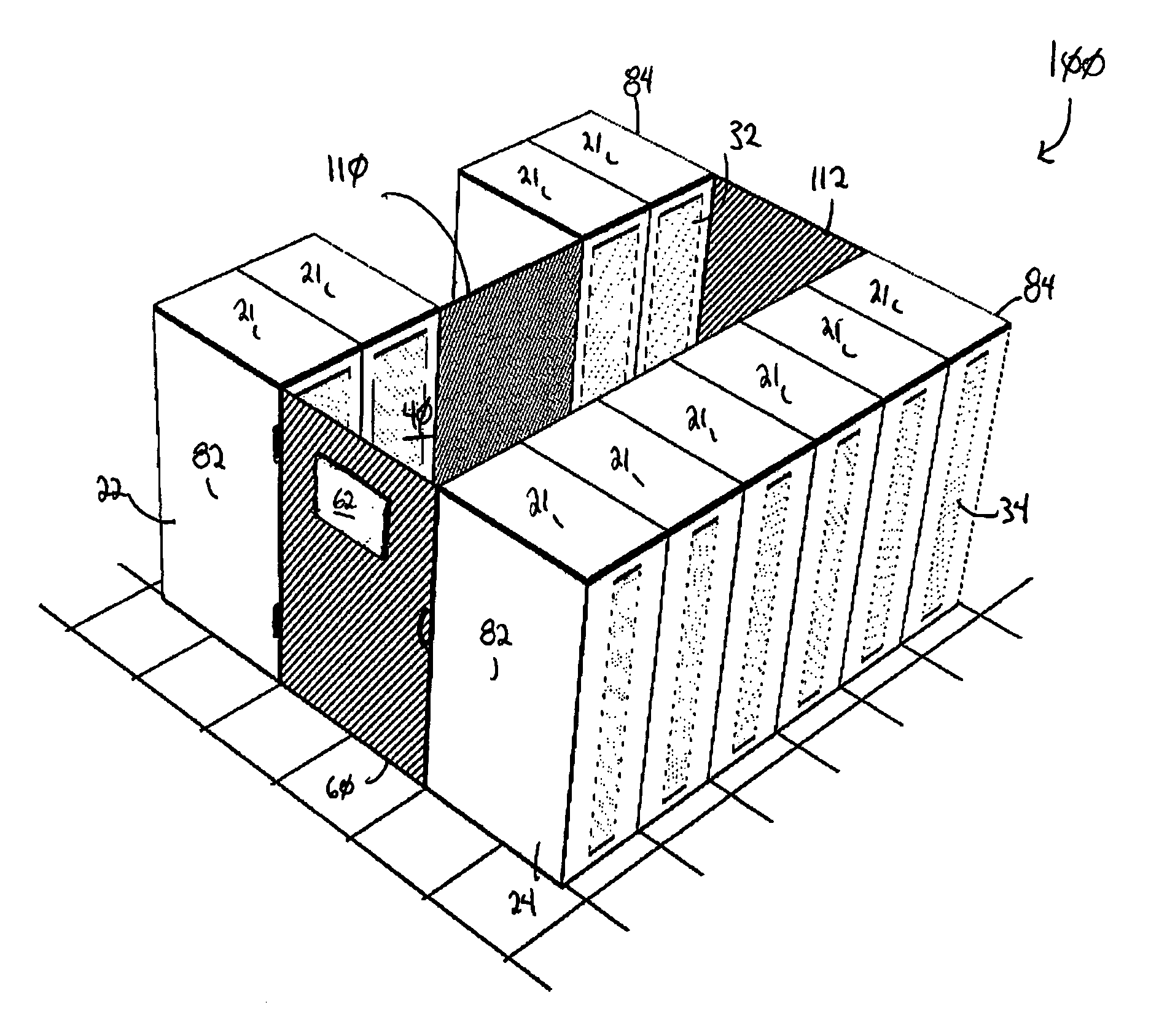
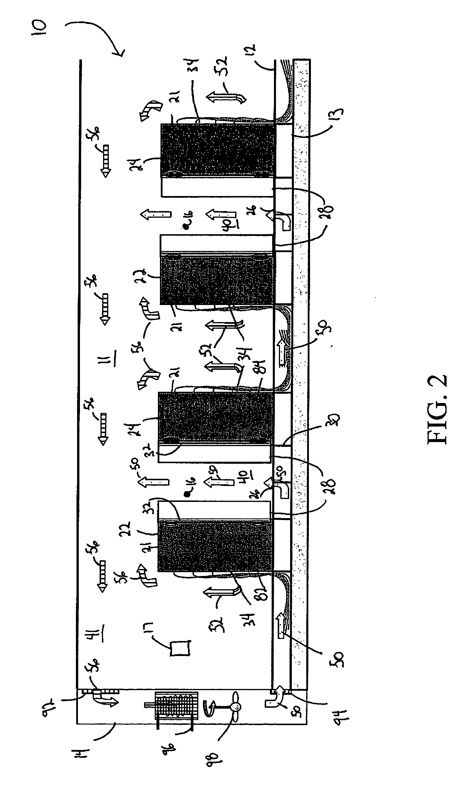
[0010] In general, in another aspect, the invention provides a method of cooling electronic equipment contained in racks in a data center. The method includes providing cool air to a first region between two rows of racks, including a first row and a second row that is substantially parallel to the first row, with a front face of at least one of the racks of the first row facing towards a front face of at least one of the racks of the second row, inhibiting the cool air from horizontally exiting from the first region through a gap between a first rack of the first row and a first rack of the second row, exhausting warm air from the electronic equipment out of at least one of the racks in at least one of the rows, inhibiting the warm air from horizontally entering the first region through the gap, and allowing a person to access the first region via the gap.
[0014] In accordance with implementations of the invention, one or more of the following capabilities may be provided. Existing data centers can be easily modified in accordance with the invention. Different cooling needs of particular data centers can be accommodated. Mixing of cool air and warm exhaust air in a data center can be inhibited. A data room can be modified in accordance with the invention with little or no modification to its structure, e.g., data center lighting, sprinkler systems, security systems, etc. Data center cooling efficiency can be improved. Data centers with higher capacity relative to traditional data center arrangements can be realized. Horizontal and / or vertical cooling distribution can be more even relative to prior systems. Cooling performance can be less dependent on rack installation locations, and more rack installation locations may be utilized than in prior data centers.

Problems solved by technology

Most rack-mounted communications and information technology equipment consumes electrical power and generates heat.
The heat collectively generated in densely packed equipment racks can have adverse effects on the performance, reliability and useful life of the equipment in the racks.
Such humidification / de-humidification systems can be expensive to install and operate.

Method used


Image

  • Cold aisle isolation
  • Cold aisle isolation
  • Cold aisle isolation

Examples


Embodiment Construction

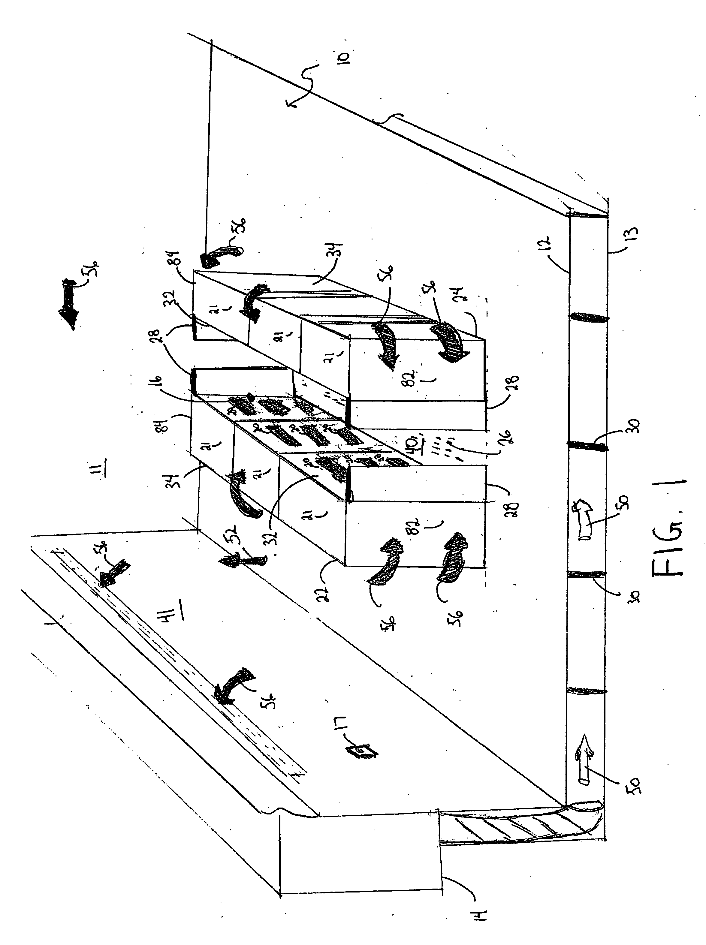
[0023] Embodiments of the invention provide techniques for inhibiting warm air from being entrained into a cold aisle in a data center. For example, a data center contains an air cooling system and a raised floor structure. The raised floor structure is configured to permit delivery of cool air into the data center through perforated tiles in the floor. Electronic equipment racks are disposed in rows on either side of the perforated tiles, such that the front side of one row faces the front side of another row with the perforated tiles located in the aisle between the front faces of the rows. A baffle extends between the rows to restrict airflow into and out of the aisle between the front faces of the rows. Other embodiments are within the scope of the invention.

[0024] Referring to FIG. 1, a data center (10) includes a room (11), a raised floor (12), a sub-floor (13), an air cooling system (14), temperature monitoring devices (16, 17), two sets of equipment racks (21) disposed in t...


PUM


Abstract

A data center cooling solution providing techniques for using baffles, doors and roof sections to prevent warm air from being entrained into a cold aisle in a data center, wherein the data center generally contains an air cooling system and a raised floor structure. The raised floor structure is configured to deliver cool air into the data center through a plurality of grates and perforated tiles in the floor. Electronic equipment racks are disposed around the grates and perforated tiles, such that the front faces of the equipment racks face the grates and perforated tiles. A collection of baffles, doors or roof sections inhibit the mixing of the cool air delivered by the air cooling system and the warm air exhausted by the electronic equipment.

Description

BACKGROUND OF THE INVENTION [0001] Communications and information technology equipment is commonly mounted in racks or enclosures. Equipment racks and enclosures are used to contain and to arrange communications and information technology equipment, such as servers, CPUs, networking equipment and storage devices in small wiring closets as well as equipment rooms and large data centers. A standard rack typically includes front-mounting rails to which multiple units of equipment, such as servers, are mounted and stacked vertically within the rack. A standard rack can be sparsely or densely populated with a variety of different components including components from different manufacturers. [0002] Most rack-mounted communications and information technology equipment consumes electrical power and generates heat. The heat collectively generated in densely packed equipment racks can have adverse effects on the performance, reliability and useful life of the equipment in the racks. According...

Claims


Application Information

Patent Timeline
IPC IPC(8): F25D23/12F25D17/04
CPCF25D17/045H05K7/20745G06F1/20F25D2317/0661
Inventor VANGILDER, JAMESGERMAGIAN, MARK
Owner SCHNEIDER ELECTRIC IT CORP
Learn More