Gas insulated breaking device

a technology of breaking device and gas insulation, which is applied in the direction of air breaking switch, contact, semiconductor device, etc., can solve the problems of difference in plating hardness between silver platings, inability to completely suppress wear, and inability to choose one. , to achieve the effect of favorable slide state and favorable electrical contact sta

Inactive Publication Date: 2006-11-23
MITSUBISHI ELECTRIC CORP
View PDF10 Cites 16 Cited by
  • Summary
  • Abstract
  • Description
  • Claims
  • Application Information

AI Technical Summary

Benefits of technology

[0025] According to the present invention, by constituting the silver plating film which is formed in the slide contact portion of the puffer cylinder and the silver plating film which is formed on the slide contact portion of the electricity supply means which supplies electricity to the puffer cylinder using the plating films having hardnesses different from each other, it is possible to provide the gas insulated breaking device which can optimize the measure to cope with a wear.
[0026] According to the present invention, it is possible to obtain a gas insulated breaking device which can realize the favorable electrical contact stat and, at the same time, can maintain the favorable slide state.

Problems solved by technology

However, it is impossible to completely suppress the wear and it is necessary to perform the silver plating treatment with plating thickness corresponding to the slide condition required by the device.
In general, however, plating treatments of both parts are processed with lots different from each other and hence, there arises difference in plating hardness between these silver platings although the difference is trivial.
Since which one of the plating film of the puffer cylinder and the plating film of the finger contact assumes a larger value depends on the number of manufacturing lots, it is not always possible to choose one of them.
Since the hardnesses depend on the number of manufacturing lots, when the slide portion of an arbitrarily gas insulated breaker is taken as an example, it is difficult to determine which one of the plating film of the puffer cylinder and the plating film of the finger contact exhibits more hardness.
However, the part which is worn in an actual apparatus is either one of the plating film of the puffer cylinder and the plating film of the finger contact and hence, there has been a drawback that another plating film possesses an unnecessarily large thickness.
Accordingly, when the silver plating is formed of the soft film, the wear attributed to sliding is increased and hence, there arises a drawback that it is necessary to preliminarily increase the thickness of the silver plating film and, at the same tine, the worn powder constitutes metal foreign substances and lowers the insulation performance of the apparatus.
However, compared to the hard film, the wear quantity is still large and hence, the wear quantity reduction effect is not less than optimum.

Method used


Image

  • Gas insulated breaking device
  • Gas insulated breaking device
  • Gas insulated breaking device

Examples


embodiment 1

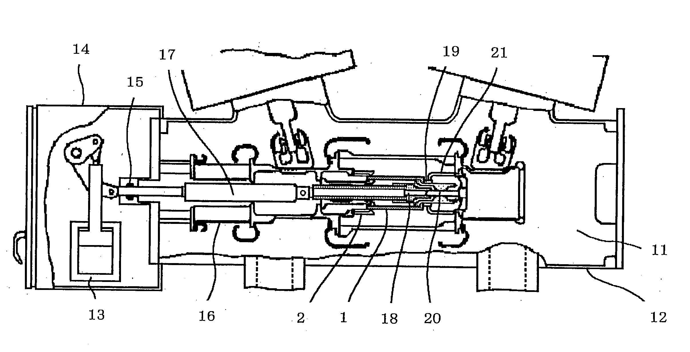
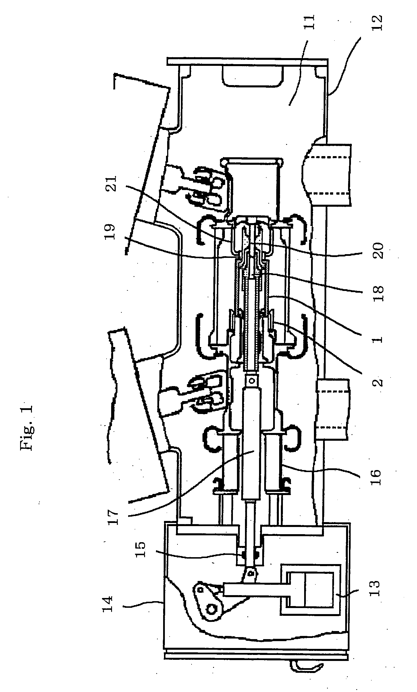
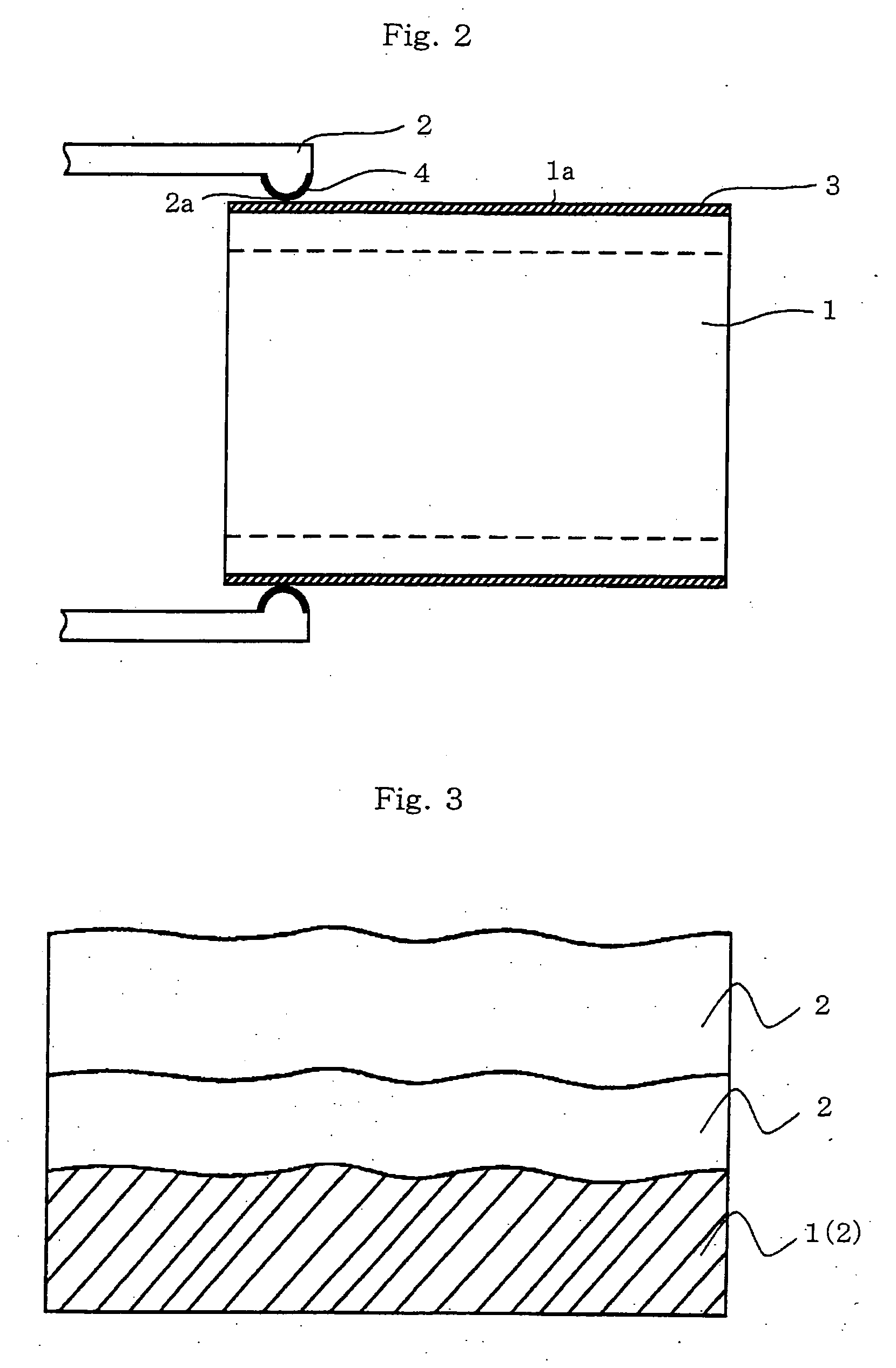
[0034] An embodiment 1 according to the present invention is explained in conjunction with FIG. 1 and FIG. 2. FIG. 1 is a side view showing one example of a puffer type gas insulated breaker which includes an arc-extinguishing chamber of a two-directional blow method to which the embodiment 1 of the present invention is applied. FIG. 2 is a cross-sectional view showing one example of the constitution of a slide portion of a gas insulated breaker according to the first embodiment of the present invention. Here, in FIG. 1 and FIG. 2, same symbols indicate identical parts.

[0035] In FIG. 1 which shows one example of the puffer type gas insulated breaker which includes the arc-extinguishing chamber of the two-directional blow method to which the present invention is applied, the gas insulated breaking device is constituted of a grounded tank 12 in which a SF6 gas 11 which constitutes an insulating medium is sealed and a manipulation housing 14 which accommodates a manipulation device 13...

embodiment 2

[0056] An embodiment 2 according to the present invention is explained in conjunction with FIG. 3 to FIG. 6. FIG. 3 is a cross-sectional view showing one example of the constitution of a slide portion of a gas insulated breaker according to the second embodiment of the present invention. FIG. 4 is a schematic view which microscopically depicts one example of a contact state of a slide contact portion. FIG. 5 is a diagram showing one example of evaluation result on wear characteristics of a silver plating film according to the second embodiment of the present invention. FIG. 6 is a diagram showing one example of evaluation result on contact resistance of the silver plating film according to the second embodiment of the present invention. FIG. 2 which is described previously is also a side view which shows the constitution of one example of a puffer type gas insulated breaking device which includes an arc-extinguishing chamber of a two-directional blow method to which the second embod...


PUM


Abstract

In a gas insulated breaking device which accommodates open/close elements including a puffer cylinder which compresses an insulation gas and extinguishes an arc and an electricity supply means which has a slide contact portion which is brought into slide contact with a slide contact portion of the puffer cylinder in the inside of a vessel in which the insulation gas is sealed, a relatively soft plating film is formed on the slide contact portion of the puffer cylinder, and a relatively hard plating film is formed on the slide contact portion of the electricity supply means, and the silver plating film of each slide contact portion has an inner layer thereof formed of a soft film and an outer layer thereof which constitutes a surface portion formed of a hard film.

Description

BACKGROUND OF THE INVENTION [0001] 1. Field of the Invention [0002] The present invention relates to a gas insulated breaking device, and more particularly to silver plating which is formed on a slide contact portion with respect to a gas insulated breaking device which is used in a power transforming field of a power system. [0003] 2. Description of the Related Art [0004]FIG. 2 is a side view showing the constitution of a puffer type gas insulated breaking device which includes an arc-extinguishing chamber of a two-directional blow method to which the present invention is applicable, and the basic constitution of the breaker has been well known as a related art. [0005] In FIG. 2, the gas insulated breaking device is constituted of a grounded tank 12 in which a SF6 gas 11 which constitutes an insulating medium is sealed and a manipulation housing 14 which accommodates a manipulation device 13 therein, wherein a manipulation force is transmitted through a shaft seal 15. A driving for...

Claims


Application Information

Patent Timeline
Patent Type & Authority Applications(United States)
IPC IPC(8): H01L31/00
CPCH01H1/023H01H1/60H01H1/385
Inventor NAGAO, EIICHIKAWADA, MAKIKOMINAGAWA, TADAOTSUCHIE, EIOHTSUKA, KYOICHI
Owner MITSUBISHI ELECTRIC CORP
Why Eureka
Try Eureka