Oxygen filling apparatus

a technology of oxygen generator and filling apparatus, which is applied in the field of oxygen generator, can solve the problems of high cost of traditional oxygen generating plants such as those used by commercial oxygen suppliers, prohibitive cost for end-users, and inability to meet the needs of end-users, so as to achieve the effect of reducing problems and inefficiencies

Inactive Publication Date: 2006-11-23
AUDUBON MACHINERY CORP
View PDF12 Cites 69 Cited by
  • Summary
  • Abstract
  • Description
  • Claims
  • Application Information

AI Technical Summary

Benefits of technology

[0008] The general object of the invention is to provide an oxygen filling apparatus which provides medical-grade oxygen. Another object is to provide an oxygen filling apparatus configured for wall mounting. It is a further object of the invention to provide an oxygen filling apparatus having a novel graphical user interface that will minimize the problems and inefficiencies associated with the prior art.

Problems solved by technology

Traditional oxygen generating plants such as those used by commercial oxygen suppliers are very costly and the purchase or installation of such a plant is impractical for even industrial end-users, and cost prohibitive for end-users such as EMS and ambulance services, hospitals and remote clinics, fire departments, nursing homes, veterinary and animal hospitals, dental labs and SCUBA applications.
Traditional oxygen cylinder delivery methods have significant drawbacks as well.
In addition to the cost of oxygen, traditional delivery methods result in significant transportation and maintenance costs, hazardous material handling fees from commercial suppliers, lease or rental fees on the actual oxygen cylinders themselves, and labor costs associated with cylinder returns and refills.
Prior art patents do not address these deficiencies.
The charging system in Cao, however, does not generate oxygen.

Method used


Image

  • Oxygen filling apparatus
  • Oxygen filling apparatus
  • Oxygen filling apparatus

Examples


Embodiment Construction

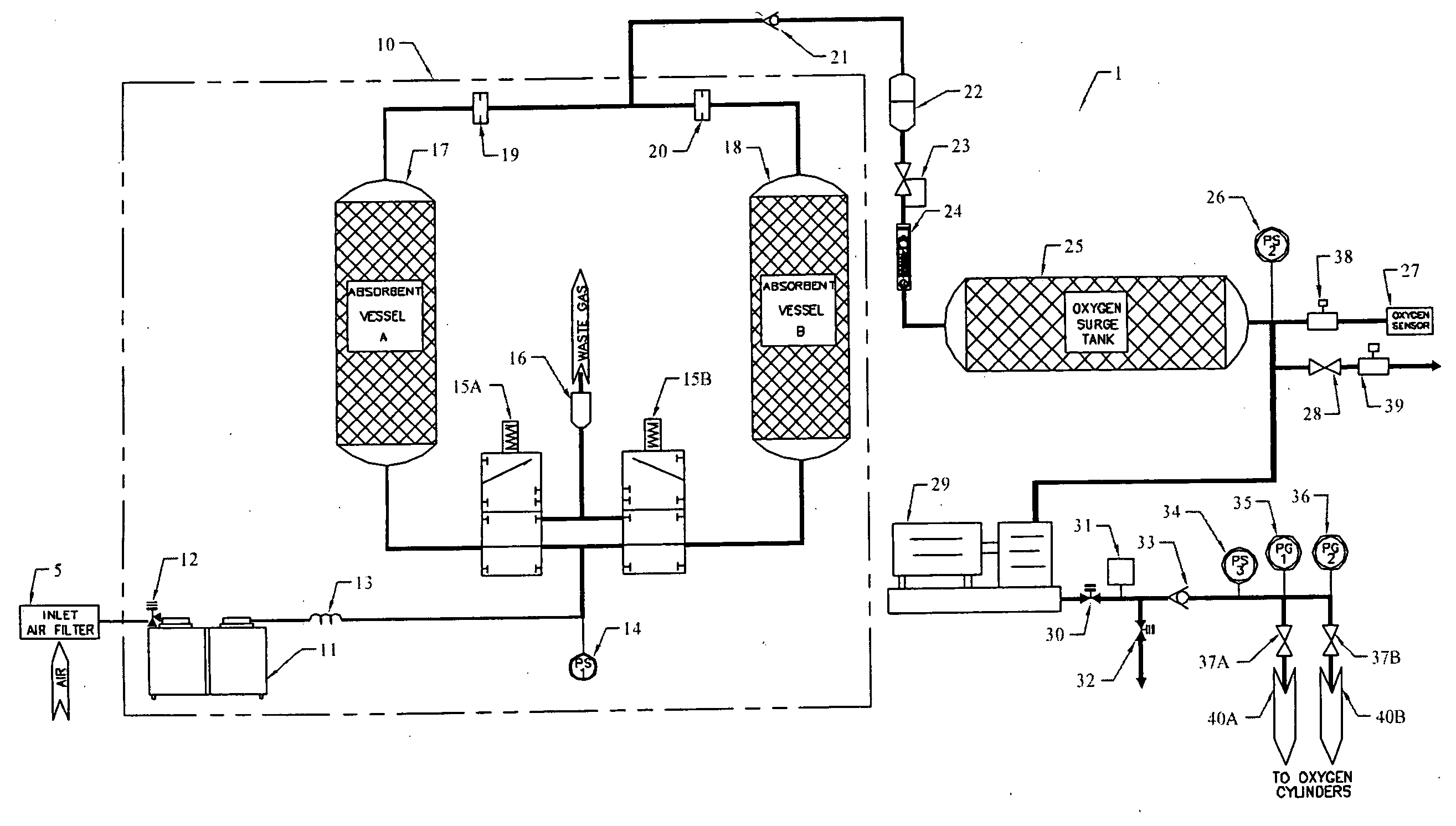
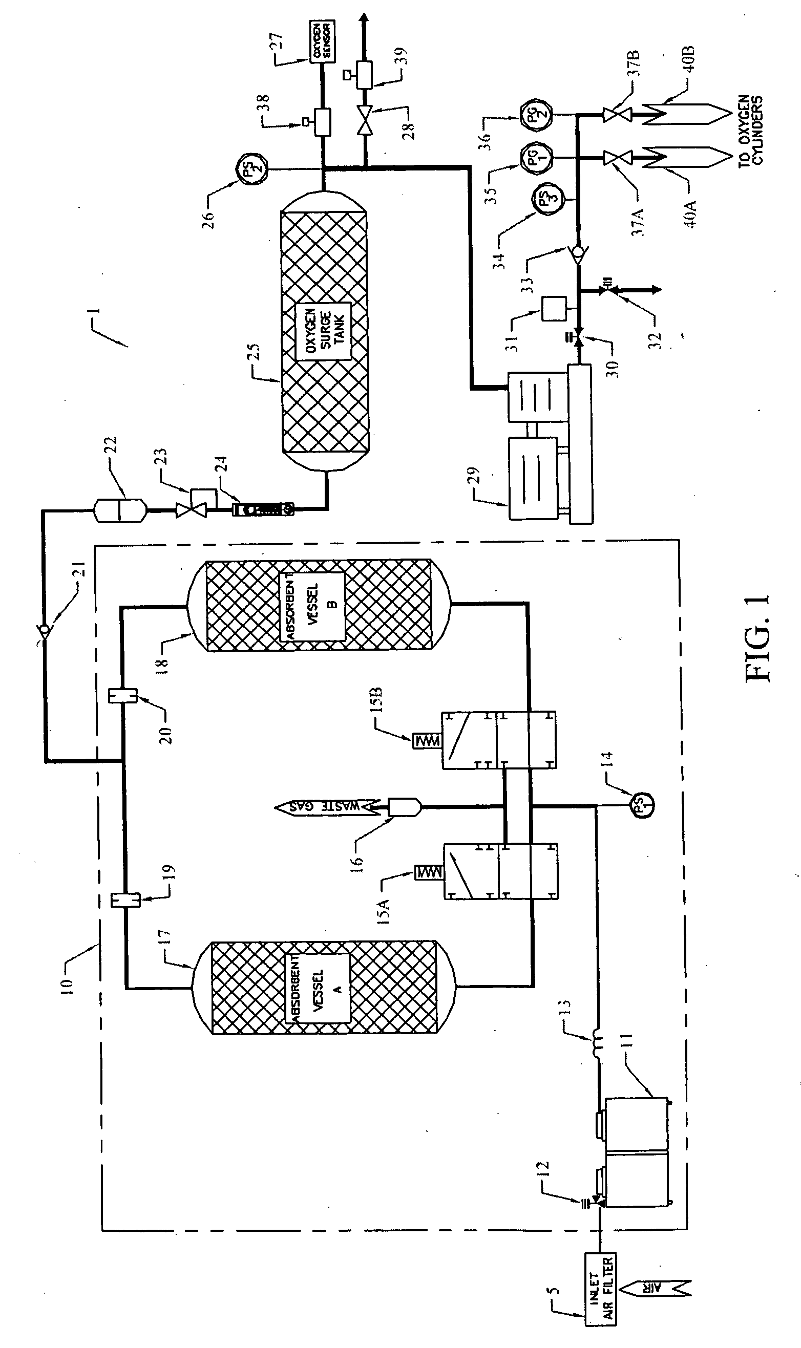
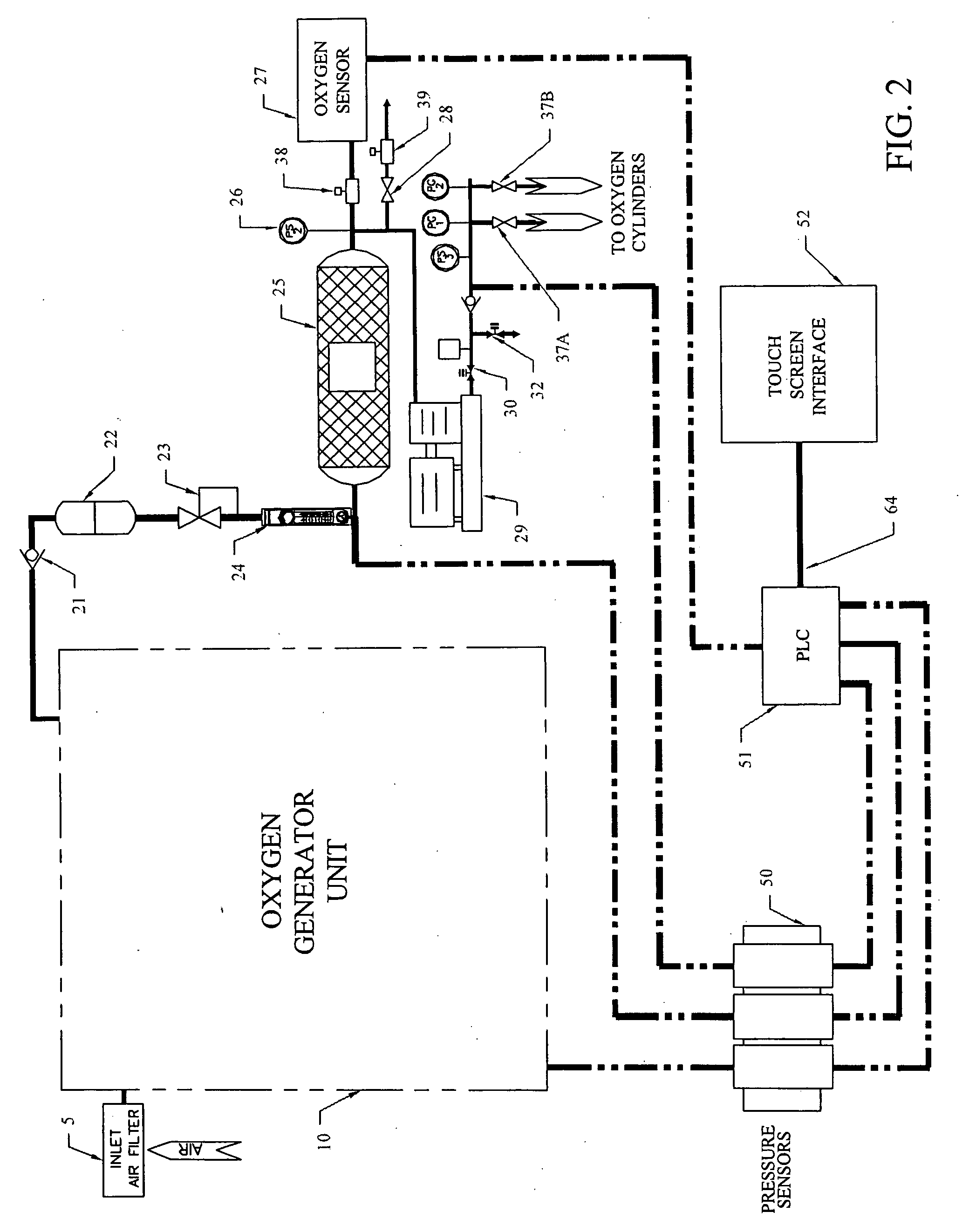
[0017] At the outset, it should be clearly understood that like reference numerals are intended to identify the same structural elements, portions or surfaces consistently throughout the several drawing figures, as such elements, portions or surfaces may be further described or explained by the entire written specification, of which this detailed description is an integral part. Unless otherwise indicated, the drawings are intended to be read (e.g., cross-hatching, arrangement of parts, proportion, degree, etc.) together with the specification, and are to be considered a portion of the entire written description of this invention. As used in the following description, the terms “horizontal”, “vertical”, “left”, “right”, “up” and “down”, as well as adjectival and adverbial derivatives thereof (e.g., “horizontally”, “rightwardly”, “upwardly”, etc.), simply refer to the orientation of the illustrated structure as the particular drawing figure faces the reader. Similarly, the terms “inw...


PUM


Abstract

The present invention provides an improved oxygen filling apparatus adapted to provide oxygen to oxygen cylinders for use in connection with EMS services, ambulances, fire departments, hospitals, veterinary clinics and other services and applications. The present invention includes an oxygen generator unit having at least one molecular sieve, a plurality of pressure sensors, an oxygen sensor, and a PLC control unit with a touch sensitive graphical screen interface configured to selectively display current and historical operational parameters. The oxygen filling apparatus may be adapted for wall mounting and may include a data communications port for remote access, monitoring and troubleshooting.

Description

TECHNICAL FIELD [0001] The present invention relates generally to the field of oxygen generators and, more particularly, to an improved oxygen generator adapted to provide oxygen to oxygen cylinders for use in connection with emergency medical services (EMS), ambulances, hospitals, dental labs, fire departments, nursing homes, veterinary clinics, SCUBA equipment, laboratories, and other services and applications. BACKGROUND OF THE INVENTION [0002] Typically, oxygen is generated commercially by fractionalization or cryogenic processes, and then stored in cylinders. Filled oxygen cylinders are delivered to end-users by commercial oxygen generators or suppliers, then returned when exhausted (or, more often, partially exhausted) and replaced with new cylinders. Traditional oxygen generating plants such as those used by commercial oxygen suppliers are very costly and the purchase or installation of such a plant is impractical for even industrial end-users, and cost prohibitive for end-us...

Claims


Application Information

Patent Timeline
Patent Type & Authority Applications(United States)
IPC IPC(8): B65B31/00
CPCF17C5/06F17C2270/02F17C2205/0329F17C2205/0332F17C2205/0338F17C2205/0341F17C2221/011F17C2221/031F17C2223/0123F17C2227/0157F17C2227/043F17C2250/032F17C2250/043F17C2250/0447F17C2250/0452F17C2250/0626F17C2250/0636F17C2250/0642F17C2250/0647F17C2201/0109
Inventor FRY, JAMES A.KIGGINS, SEAN T.MCMAHON, JOSEPH M.
Owner AUDUBON MACHINERY CORP
Why Eureka
Try Eureka