Filter element

a filter element and filter element technology, applied in the field of filters, can solve the problems of leakage between the unfiltered and the filtered side, high price and the loading of the cap, and wear-through of the free end of the filter element at the housing wall,

Inactive Publication Date: 2006-11-23
MANN HUMMEL GMBH
View PDF6 Cites 13 Cited by
  • Summary
  • Abstract
  • Description
  • Claims
  • Application Information

AI Technical Summary

Benefits of technology

[0004] Accordingly, it is an object of the present invention to provide an improved fil...

Problems solved by technology

Radial oscillations of the free end of the filter element within the housing would cause either leaks in the region of the opposite radial seal or wear-through of the free end of the filter element at the housing wall.
In the course of such wear the filter m...

Method used


Image

  • Filter element
  • Filter element

Examples


Embodiment Construction

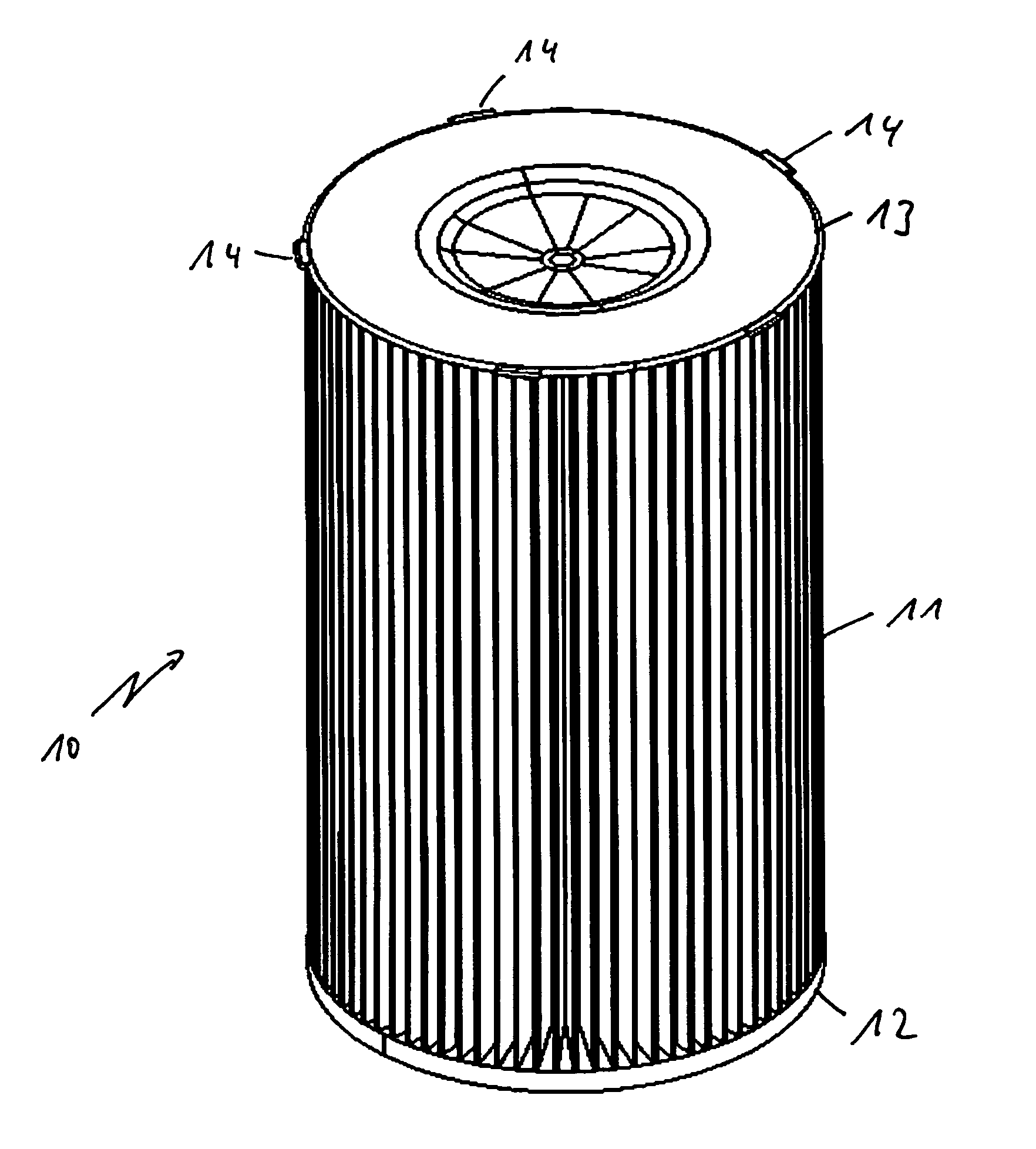
[0019]FIG. 1 is an isometric view of a filter 10 according to the invention. The filter 10 has a fan folded filter medium 11, which is closed at its one end face by a first end disk 12 and at the opposite end face by a second end disk 13. The first end disk 12 has an opening (not shown) in its interior with an inside sealing contour for receiving a connection fitting in the housing (not shown). The second end disk 13 is closed and has a plurality of spacing contours 14 distributed over its circumference. These spacing contours 14 extend radially beyond the projected end face of the filter 10 and are formed integrally directly with the second end disk 13.

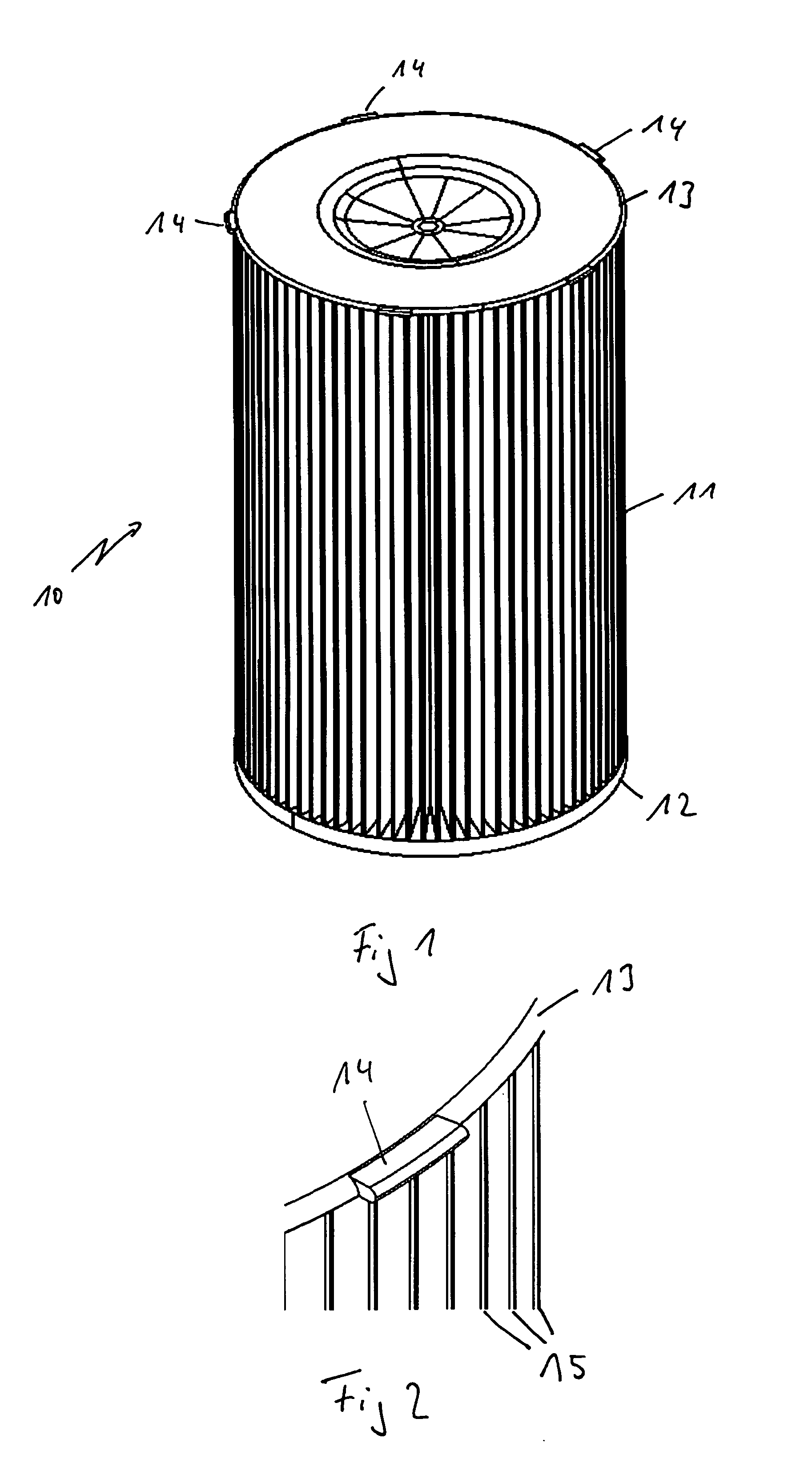
[0020]FIG. 2 shows a detail in the region of the second end disk 13 of the filter 10. Components corresponding to those of the preceding figure are identified by the same reference numerals. It may be seen that the second end disk 13 delimits and seals the filter medium 11. The individual folds 15 of the filter medium 11 are visible...


PUM

PropertyMeasurementUnit
Circumferenceaaaaaaaaaa

Abstract

A filter suitable for use, for example, as an air filter for filtering the combustion air for internal combustion engines, having a substantially hollow cylindrical filter insert, preferably made of a pleated or fan folded filter medium, and end disks disposed at the axial end faces. A plurality of spacing contours distributed around the circumference and protruding radially beyond the projected end face are disposed in the region of one end disk in such a way that the spacing contours contact an inner housing wall of an associated filter housing when the filter insert is installed.

Description

BACKGROUND OF THE INVENTION [0001] The present invention relates to a filter, particularly an air filter, preferably for filtering the combustion air for internal combustion engines, comprising a hollow cylindrical filter medium with end disks on each of its axial end faces. [0002] U.S. Pat. No. 5,660,729 (=DE 44 16 577) discloses a filter insert for a filter for filtering liquid or gaseous media. This filter insert has a substantially hollow cylindrical filter body, through which the medium to be filtered flows in radial direction, and two end disks at its respective end faces. One of the end disks is provided with a central opening and can be axially placed onto a media inlet or outlet fitting so as to form a radial seal. The opposite end disk is closed, and the end disks are made of a thermally recyclable plastic. The closed end disk further has a latching recess adapted to receive latching counter elements of a screw cap of an associated filter housing or a removal tool. This la...

Claims


Application Information

Patent Timeline
IPC IPC(8): B01D29/07B01D46/00
CPCB01D29/21B01D46/2414B01D2279/60B01D2271/027B01D46/521
Inventor DWORATZEK, KLEMENSBAUDER, RALFMUENKEL, KARLHEINZWAGNER, UDO
Owner MANN HUMMEL GMBH
Why Eureka
Try Eureka