Single wafer cleaning method to reduce particle defects on a wafer surface

a single-wallet cleaning and particle defect technology, applied in the direction of cleaning using tools, cleaning using liquids, chemistry apparatus and processes, etc., can solve the problems of reducing the useful life of the chemical bath, affecting the cleaning effect, and provoking cross contamination between wafers, so as to reduce the number of surface defects, reduce or eliminate particle defects, and reduce the effect of particle defects

Inactive Publication Date: 2006-11-23
APPLIED MATERIALS INC
View PDF6 Cites 8 Cited by
  • Summary
  • Abstract
  • Description
  • Claims
  • Application Information

AI Technical Summary

Benefits of technology

[0009] A single wafer cleaning method is described to reduce particle defects on the wafer surface. According to one embodiment of the invention, the method includes minimizing the number of surface defects on a wafer by minimizing the number of air-liquid interfaces that the wafer may experience during a single-wafer wet cleaning process. This is especially important for wafers with a hydrophobic surface. Additionally, according to another embodiment of the invention, the method includes reducing or eliminating particle defects deposited on the wafer surface by minimizing reactions between the etch species and the wafer in a cleaning solution during a pH transition.

Problems solved by technology

Due to the increasingly stringent requirements of wafer surface cleanliness, the limitations of such immersion cleaning are now being challenged.
A limitation of immersion cleaning is the build up of contamination during the useful life of the chemical bath by the particles removed from the wafers being cleaned.
Inherently, immersion cleaning invites cross contamination between wafers as well as contamination of the chemical bath itself.
However, even using fresh chemicals for every batch, in addition to being very expensive, would not completely eliminate the issue of cross-contamination.
However, even single-wafer cleaning faces challenges.
However, during cleaning and rinsing, etched species or particulates tend to collide with the wafer surface causing particle defects.
Hence, keeping the particles off the wafer surface is a challenge.

Method used


Image

  • Single wafer cleaning method to reduce particle defects on a wafer surface
  • Single wafer cleaning method to reduce particle defects on a wafer surface
  • Single wafer cleaning method to reduce particle defects on a wafer surface

Examples


Embodiment Construction

[0019] Described herein is a single wafer cleaning method. In the following description numerous specific details are set forth. One of ordinary skill in the art, however, will appreciate that these specific details are not necessary to practice embodiments of the invention. While certain exemplary embodiments of the invention are described and shown in the accompanying drawings, it is to be understood that such embodiments are merely illustrative and not restrictive of the current invention, and that this invention is not restricted to the specific constructions and arrangements shown and described since modifications may occur to those ordinarily skilled in the art.

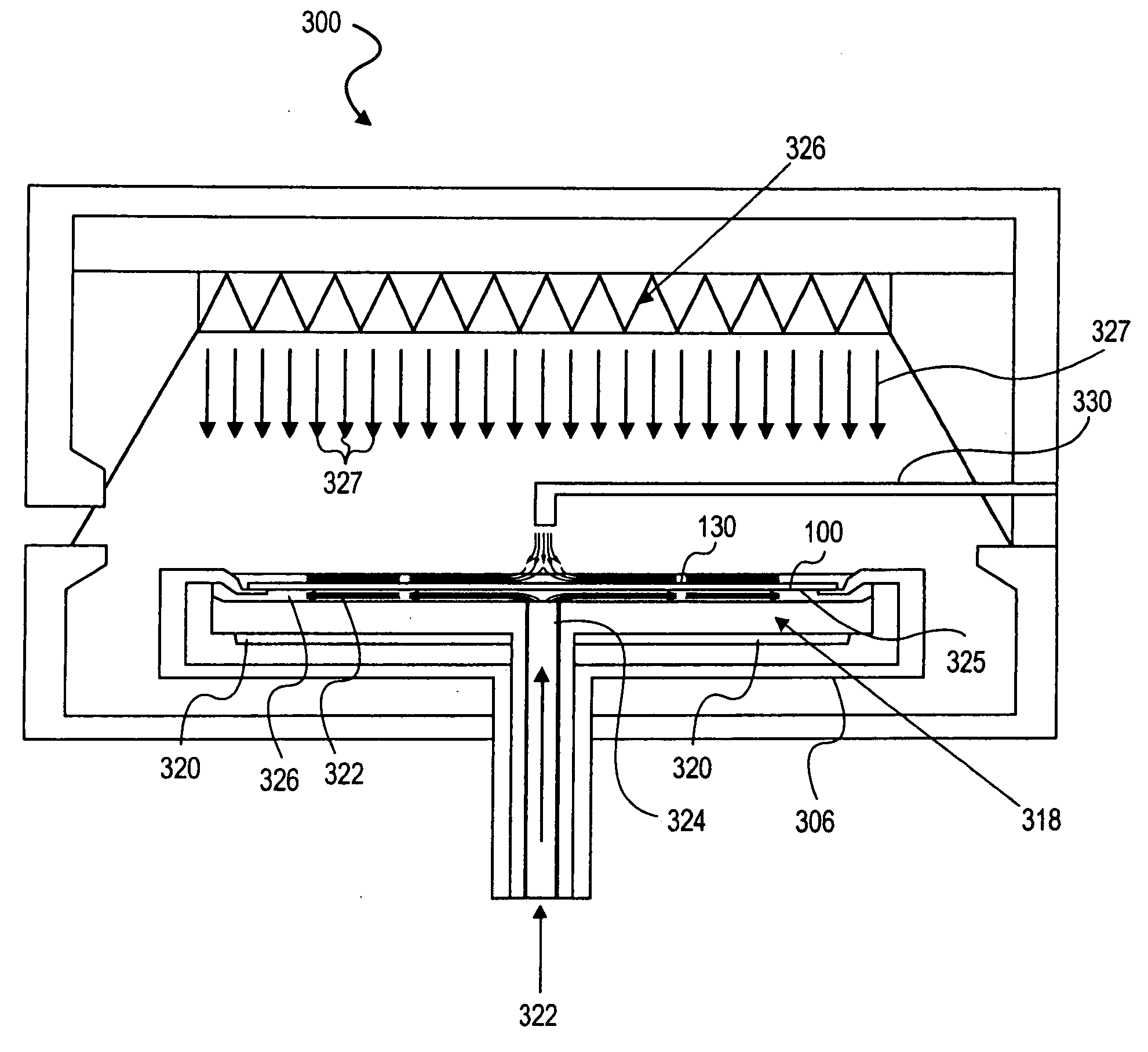
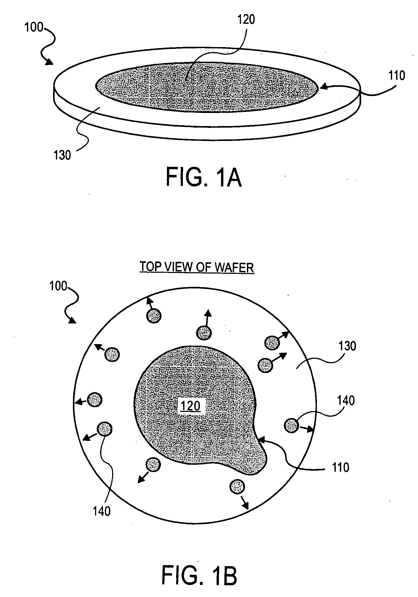
[0020] Particles may stick to the surface of a wafer during a clean in a horizontal spinning single wafer cleaning apparatus under different conditions. One set of conditions where particles may stick to the surface of the wafer is when air-liquid interfaces exist on the surface of the wafer. Air-liquid interfaces are ...


PUM

PropertyMeasurementUnit
flow ratesaaaaaaaaaa

Abstract

Methods of preventing air-liquid interfaces on the surface of a wafer in order to prevent the formation of particle defects on a wafer are presented. The air-liquid interfaces may be prevented by covering the entire surface of the wafer with liquid at all times during a cleaning process while the surface of the wafer is hydrophobic. Methods of preventing the formation of silica agglomerates in a liquid during a pH transition from an alkaline pH to a neutral pH are also presented, including minimizing the turbulence in the liquid solution and reducing the temperature of the liquid solution during the transition.

Description

[0001] This is a continuation of U.S. application Ser. No. 10 / 736,007, filed Dec. 15, 2003, which is currently pending, which claims the benefit of U.S. Provisional Application No. 60 / 434,188, filed Dec. 16, 2002.BACKGROUND OF THE INVENTION [0002] 1. Field of the Invention [0003] The present invention relates generally to the field of front-end-of-the-line wet cleaning of a semiconductor wafer. [0004] 2. Discussion of Related Art [0005] In semiconductor manufacturing, wet cleaning comprises a majority of the steps required to make a device. For many years, immersion cleaning has been the method of choice for wet cleaning. Due to the increasingly stringent requirements of wafer surface cleanliness, the limitations of such immersion cleaning are now being challenged. [0006] In immersion cleaning, a batch of wafers may be dipped into a series of chemical and rinsing baths. Traditionally, the chemistry cleaning solutions are based on the RCA cleaning method: NH4OH / H2O2 / H2O (or Standard ...

Claims


Application Information

Patent Timeline
Patent Type & Authority Applications(United States)
IPC IPC(8): B44C1/22B08B1/02C23F1/00B08B3/04B08B3/10H01L21/00H01L21/302H01L21/306H01L21/461
CPCB08B3/04H01L21/67051H01L21/02052B08B3/10
Inventor VERHAVERBEKE, STEVENBEAUDRY, CHRISTOPHER LAURENT
Owner APPLIED MATERIALS INC
Why Eureka
Try Eureka