Vending machine

a technology of vending machine and cylinder, which is applied in the direction of instruments, thin material handling, coin-freed instruments, etc., can solve the problem of extremely difficult effect of implementing these contrivances

Inactive Publication Date: 2006-11-23
SANDEN CORP
View PDF6 Cites 29 Cited by
  • Summary
  • Abstract
  • Description
  • Claims
  • Application Information

AI Technical Summary

Benefits of technology

[0011] The object of the present invention is to provide a vending machine that implements the origin detection as accurately as possible by utilizing an origin-detection method which is basically the same as a conventional method.
[0013] According to the vending machine, when the origin is detected, the speed of the movable body that moves to the origin detection position is reduced at the timing when the movable body reaches the speed-reduction position located before the respective origin detection position, and the movable body that has been decelerated activates the sensor. Therefore, compared with the case where the movable body whose speed is not reduced activates the sensor, the variation range of the activation timing when the sensor is activated can be reduced. Hence, the deviation in the origin detection position detected by the sensor can be reduced, and the origin detection can be implement as accurately as possible by utilizing the origin-detection method which is basically the same as the conventional method.

Problems solved by technology

However, when limited production costs are taken into account, implementations of these contrivances are extremely difficult in effect.

Method used


Image

  • Vending machine
  • Vending machine
  • Vending machine

Examples


Embodiment Construction

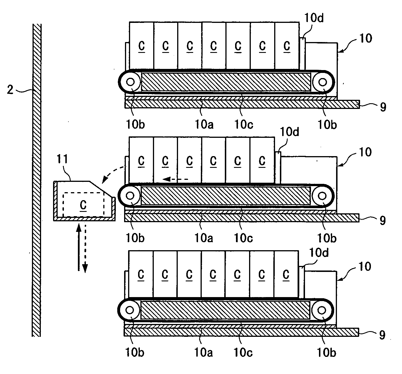
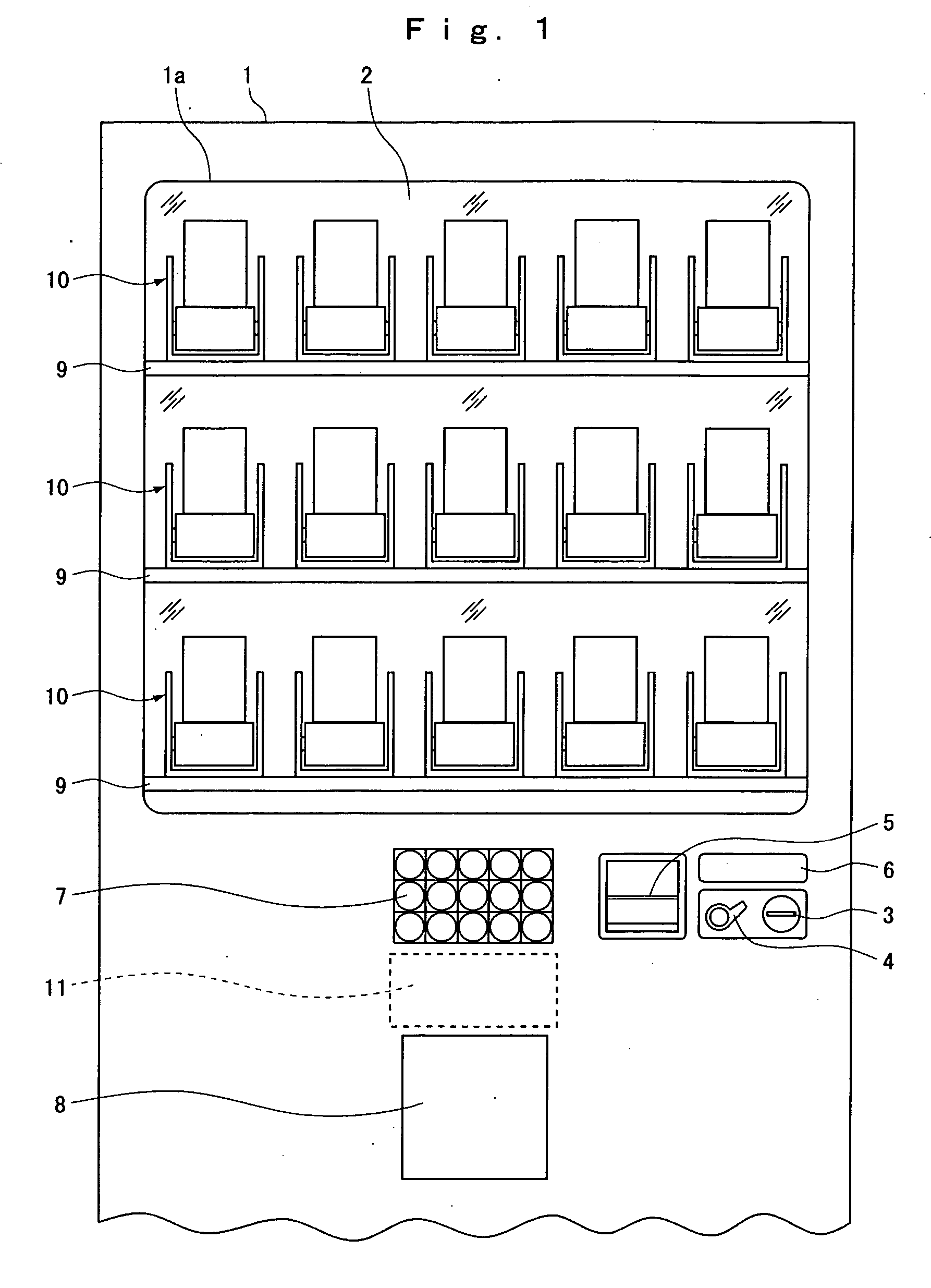
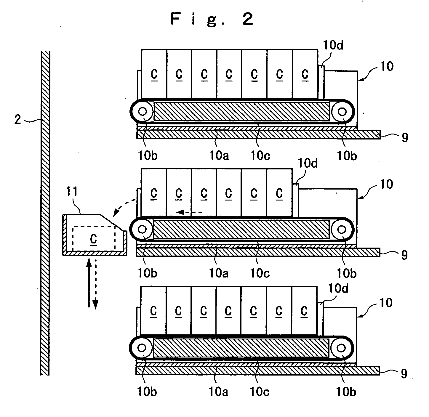
[0023] FIGS. 1 to 6 illustrate an embodiment in which the present invention is applied to a see-through vending machine. FIG. 1 is a partial front view of the see-through vending machine; FIG. 2 is a longitudinal cross-sectional view of commodity containers and a bucket in the vending machine illustrated in FIG. 1; FIG. 3 is a perspective view of the bucket and a bucket driving mechanism in the vending machine illustrated in FIG. 1; FIG. 4 is a block diagram of the vending machine illustrated in FIG. 1; and FIGS. 5 and 6 are flowcharts for origin detection implemented in the vending machine illustrated in FIG. 1.

[0024] In the first place, the mechanism of the vending machine will be explained with reference to FIGS. 1 to 3.

[0025] A cabinet 1 has a main body (no reference character) whose front face is opened and a door (no reference character) that is provided on the front opening of the main body in an openable and closable manner. A window opening 1a is formed in the front top p...


PUM


Abstract

A vending machine is configured in such a way that, the speeds of a bucket and an elevator that, upon origin detection, move to respective origin detection positions are reduced at the timing when the bucket and the elevator reach respective speed-reduction positions that are located before the respective origin detection positions, and the bucket and the elevator whose speeds have been reduced activate respective sensors. With the foregoing configuration, compared to the case where the bucket and the elevator whose speeds are not reduced activate the sensors, the respective variation ranges of the activation timings when the sensors are activated are reduced, whereby the respective deviations in the origin detection positions detected by the sensors are reduced.

Description

BACKGROUND OF THE INVENTION [0001] 1. Field of the Invention [0002] The present invention relates to a vending machine that provides a consumer with a selected commodity based on a money insertion and a commodity selection. [0003] 2. Description of the Related Art [0004] Some vending machines includes, as a mechanism for providing a consumer with a selected commodity, a movable body capable of linearly moving in a predetermined direction and a movable-body driving mechanism having a motor as a driving source. [0005] For example, a vending machine termed a see-through type has a plurality of commodity containers arranged in a matrix viewed from the front, a bucket capable of linearly moving in a X direction (a right-and-left direction) and in a Z direction (a up-and-down direction), and a bucket driving mechanism for moving the bucket in a two-dimensions within the XZ-coordinate system. [0006] The bucket driving mechanism has an X-axis driving mechanism for moving the bucket in the X...

Claims


Application Information

Patent Timeline
Patent Type & Authority Applications(United States)
IPC IPC(8): G07F11/00
CPCG07F11/58
Inventor MATSUMOTO, NAOTOOHKUBO, MASARU
Owner SANDEN CORP
Why Eureka
Try Eureka