
Actuator and material for the actuator

a technology of actuators and actuators, applied in the field of actuator modules, can solve the problems of difficult control of temperature by heating under electric supply, slow response, and difficulty in obtaining large expansion and contraction within a practical temperature range, and achieve good controllability

Inactive Publication Date: 2006-11-23
HITACHI LTD
View PDF8 Cites 40 Cited by
  • Summary
  • Abstract
  • Description
  • Claims
  • Application Information

AI Technical Summary

Benefits of technology

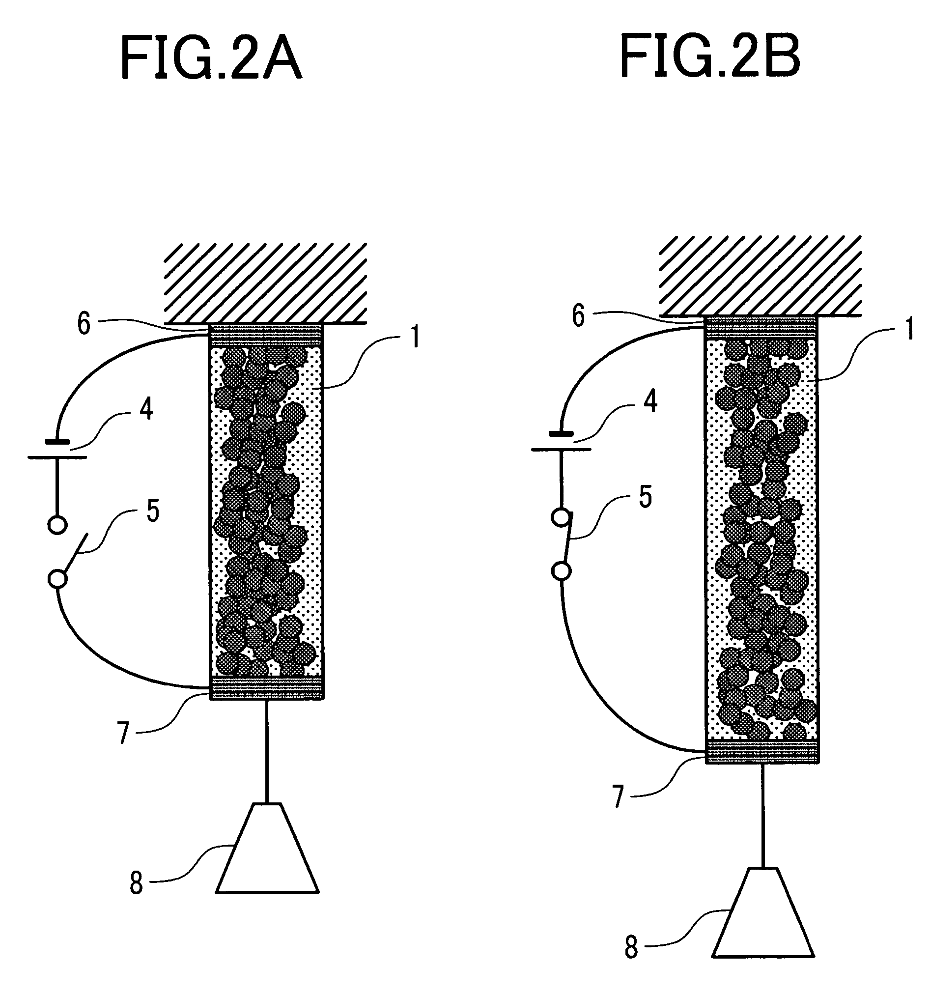
The present invention provides an actuator that can operate stably in a gas phase such as in air with safety, can be micro-miniaturized, controlled satisfactorily, and reduced in weight. The actuator uses a material of high thermal expansion coefficient and high electric conductivity, which allows for self heat generation by electric supply and conducts expanding and contracting operation by utilizing the deformation of the material due to large thermal expansion and contraction caused by the change of the temperature. The actuator is light weight and flexible and has good controllability.

Problems solved by technology

The actuator utilizing the organic material that deforms depending on electric signals is reduced in the weight and can be easily micro-miniaturized; however, it involves several problems in view of operating circumstance and controllability.
Since deforming by desorption of molecules such as of water, however, the actuator involves a problem in that the operation greatly depends on the surrounding circumstance such as humidity and the response is slow as well.
Since a polymer material of high thermal expansion coefficient is an insulator, control of the temperature by heating under electric supply is difficult.
In addition, since the material such as a metal of high electric conductivity has small thermal expansion coefficient, it is difficult to obtain large expansion and contraction within a practical range of temperature.

Method used


Image

  • Actuator and material for the actuator
  • Actuator and material for the actuator
  • Actuator and material for the actuator

Examples


embodiment 1

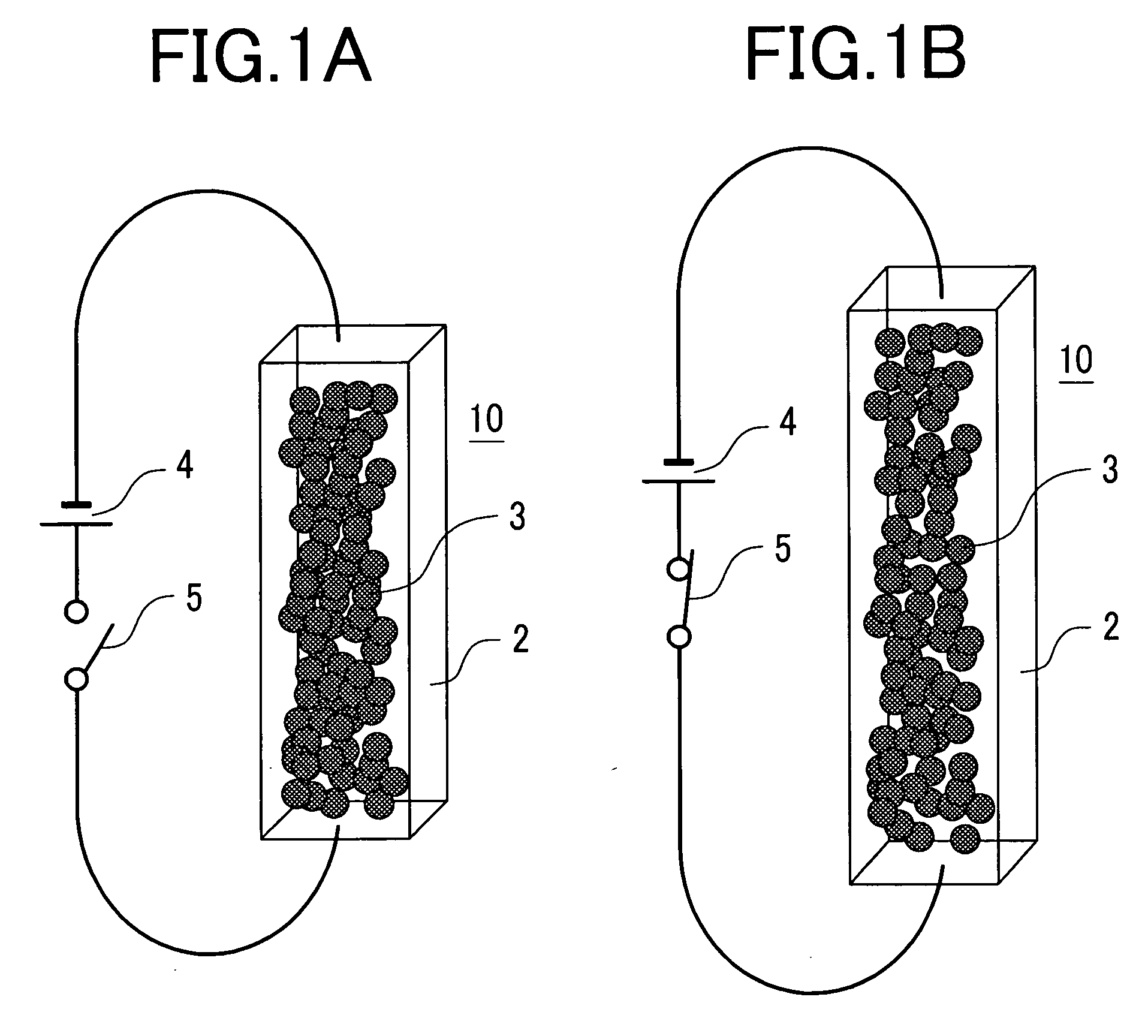
[0048] In Embodiment 1, the concept of the basic operation of an actuator according to the invention and a manufacturing method thereof are to be described. At first, a description is to be made of the deformation of an actuator material when a voltage is applied to the actuator material constituting the actuator of the invention.

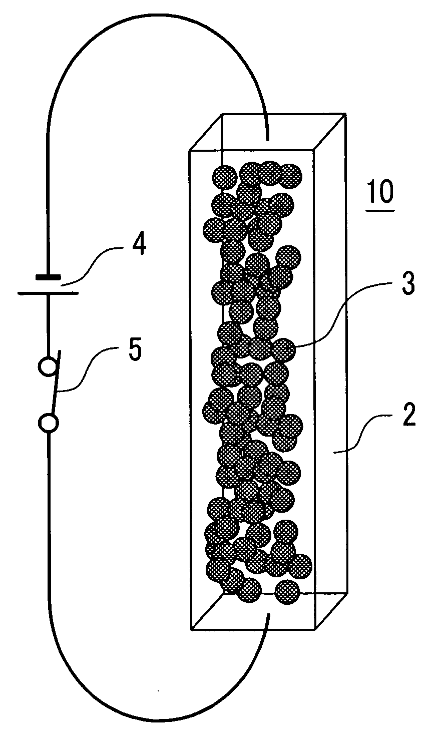
[0049]FIG. 1A schematically shows the state of an actuator material before voltage is applied thereto and FIG. 1B schematically shows the state of the actuator material when the voltage is applied. In the figures, are shown a polymer material 2 of large thermal expansion coefficient, fine conductive particles 3, and an actuator material 10 in which the fine conductive particles 3 are dispersed in the polymer material. There are also shown a power source 4 and a switch 5. Current can be supplied or stopped to the polymer material 10 by turning the switch 5 on or off. When a voltage of the power source 4 is applied to the actuator material 10 with the switch...

embodiment 2

[0077] In Embodiment 2, an actuator module structure using the actuator of the invention and an actuator matrix utilizing the same are to be described with reference to FIGS. 6A to 8B. FIGS. 6A and 6B are cross sectional views showing the concept of the actuator module structure of the invention in which FIG. 6A is a cross sectional view of an actuator module in a state before application of a voltage and FIG. 6B is a cross sectional view of the actuator module in a state upon application of the voltage. In an actuator module 60, a stretchable member 64 is disposed in an open plane of an elongate box-shaped container 65, and electrodes 62, 63 are buried in the bottom of the container 65. An actuator film 61 turned back at the central portion thereof is disposed inside the container 65, the turned back portion is joined to the lower surface of the stretchable member 64 at the upper surface of the container 65, and both ends of the actuator film 61 are joined with the respective elect...

embodiment 3

[0086] Embodiment 3 proposes a Braille display device as one of portable haptic devices as an application example of the actuator module shown in Embodiment 2, as well as a Braille display system using the same, which is to be described with reference to FIGS. 9A, 9B, 10A and 10B.

[0087] A Braille cell is expressed as a unit in which protrusions each having a height of about 0.4 mm are arranged about 2.2 mm apart to constitute a 3×2 dot matrix. The Braille display device of Embodiment 3 is a device in which six pins are arranged as a 3×2 matrix and an optional pin can be moved vertically at 0.4 mm stroke in response to electric signals.

[0088] A most simple Braille display device using the actuator module according to the invention is an actuator matrix using the actuator module 60 described in FIG. 6 for Embodiment 2 and arranging them in 3×2 arrangement. FIG. 9A is a conceptional view in which Braille display device 90 having actuator modules 60 arranged in 3×2 is viewed from abov...


PUM


Abstract

A material for an actuator is provided which is reduced in weight, can be micro-miniaturized and can be used stably in a gas phase such as in atmospheric air safely, and an actuator using the material is provided. The material used for the actuator comprises a material formed by mixing fine conductive particles with a polymer material having a large absolute value of thermal expansion coefficient.

Description

CLAIM OF PRIORITY [0001] The present application claims priority from Japanese application JP 2005-146337 filed on May 19, 2005, the content of which is hereby incorporated by reference into this application. BACKGROUND OF THE INVENTION [0002] 1. Field of the Invention [0003] The present invention relates to an actuator module reduced in weight and capable of causing deformation such as expansion and contraction, bending, or the like repetitively by electric signals, and a material used therefor. [0004] 2. Description of the Related Art [0005] Medical or nursing fields require safety actuators that can be micro-miniaturized and reduced in weight and that are flexible and operated at a low driving voltage for the application use of active catheters, endoscopes, rehabilitation aids, powered suits, artificial organs, etc. Further, paper displays and portable haptic devices for which a new demand will be expected in the future require actuators capable of attaining complicate movements ...

Claims


Application Information

Patent Timeline
Patent Type & Authority Applications(United States)
IPC IPC(8): H01L41/00G02B6/35H10N30/00G02B26/08H02N11/00
CPCA61B1/0051F03G7/06A61M25/0158Y10S310/80
Inventor KATO, MIDORIISHIBASHI, MASAYOSHI
Owner HITACHI LTD
Learn More