Switch device

a technology of switch and switch body, which is applied in the direction of measurement device, circuit interrupter testing, instruments, etc., can solve the problems that the short distance between the gate and the emitter cannot be securely recognized, and achieve the effects of simple circuit-technological measures, enhanced availability of the circuit, and high reliability

Inactive Publication Date: 2006-11-23
FRAUNHOFER GESELLSCHAFT ZUR FOERDERUNG DER ANGEWANDTEN FORSCHUNG EV
View PDF3 Cites 7 Cited by
  • Summary
  • Abstract
  • Description
  • Claims
  • Application Information

AI Technical Summary

Benefits of technology

[0008] Hence, it is an object of the present invention to provide a switch device offering an improved possibility for recognizing errors of a switch to be tested, and thus offering higher reliability and enhanced availability of the switch device.
[0018] Thus, the present invention offers the advantage of being able to completely test a switch to be tested for its operability. All potential errors can be detected by the present invention already prior to power-up of the switch to be tested. Thus, it is not required to wait for the failure case, at which greater damage might arise, during the operation of the switch to be tested when switching high powers. Thus, higher reliability and enhanced availability of the circuit can be expected. Furthermore, the present invention has the advantage that the alteration of a conventional circuit for testing the functionality can be realized only by simple circuit-technological measures, in particular by the use of two additional switch elements. The possibility of the recognition of further errors thus only requires little overhead.

Problems solved by technology

It proves disadvantageous, however, that some errors can indeed be recognized by this diagnosis (e.g. an open in the collector-emitter path), but not all occurring errors.
For example, a short between gate and emitter cannot be recognized securely.

Method used


Image

  • Switch device
  • Switch device
  • Switch device

Examples


Embodiment Construction

[0022] In the subsequent description of the preferred embodiment of the present invention, the same reference numerals will be used for similarly acting elements illustrated in the various drawings.

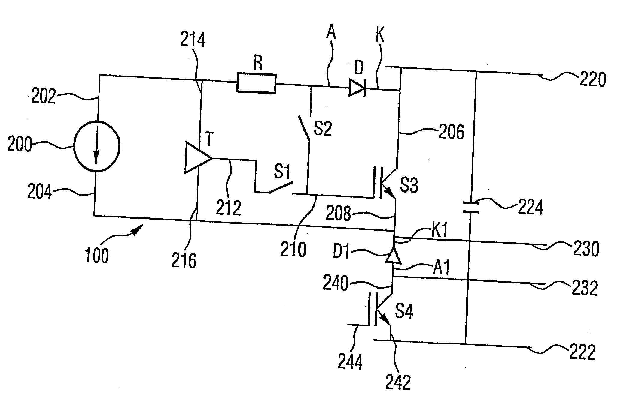
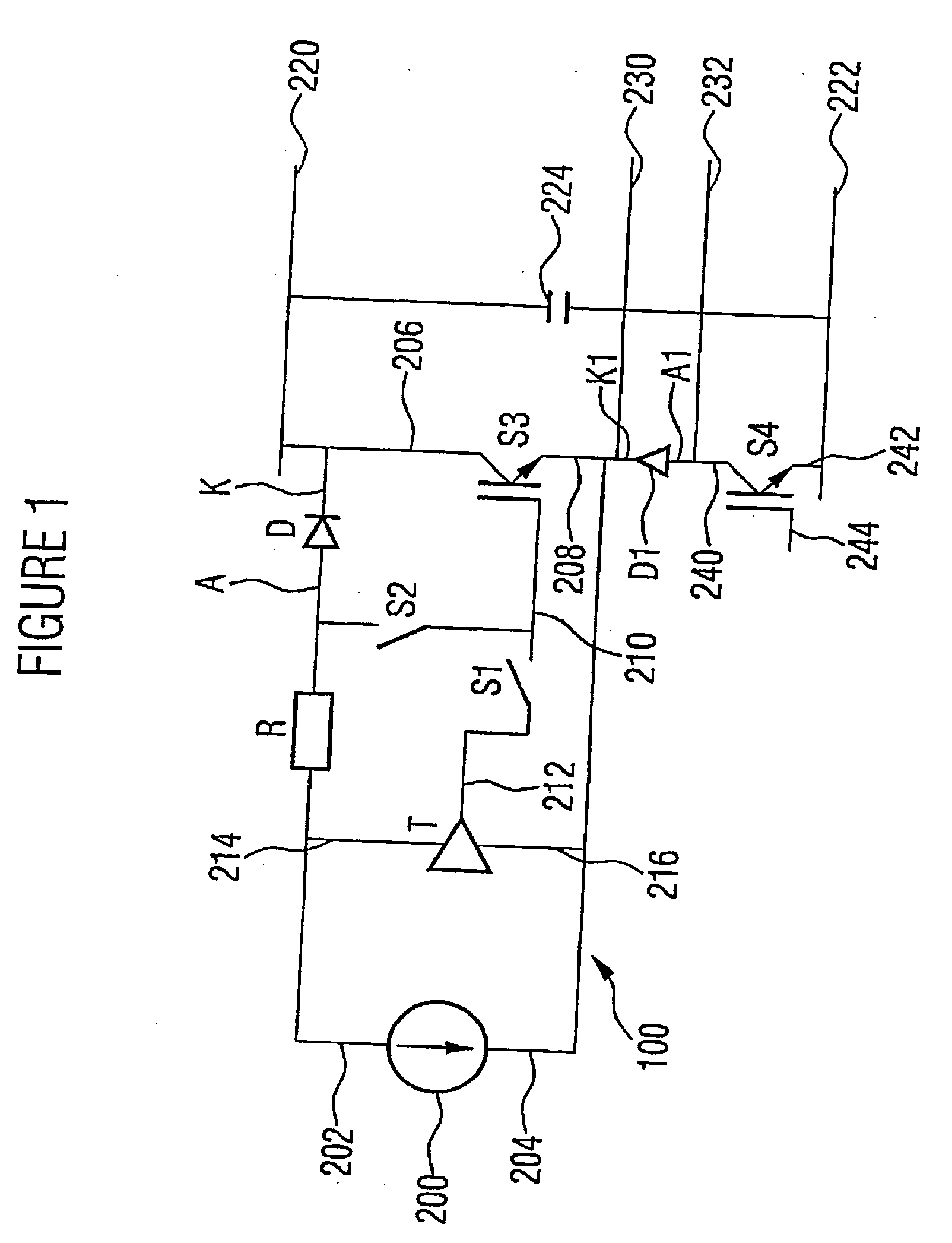
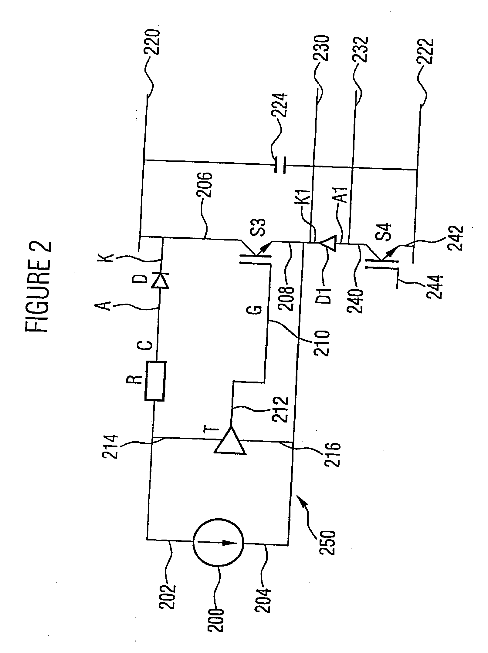
[0023] In FIG. 1, the circuit topology of a controller (switching circuit) is illustrated using a preferred embodiment of a switch device 100 according to the invention. The circuit topology of the preferred embodiment of the switch device 100 according to the invention substantially corresponds to the switch device 250 shown in FIG. 2. In contrast to the switch device 250 shown in FIG. 2, the switch device 100 illustrated in FIG. 1 comprises a second switch S2 connected between the anode A of the diode D and the control terminal 210 of the switch S3 to be tested. Furthermore, the switch device 100 comprises a third switch S1 connected between the control output 212 of the drive circuit T and the control terminal 210 of the switch S3 to be tested. The second switch S2 and the third switc...


PUM


Abstract

A switch device includes a switch to be tested with a first terminal and a second terminal as well as a control terminal for controlling a resistance between the first terminal and the second terminal. Furthermore, the switch device includes a resistor as well as means for providing a measuring current across the resistor into the first terminal of the switch to be tested, wherein the control terminal and the first terminal of the switch to be tested are coupled in electrically conductive manner. Furthermore, the switch device includes means for sensing a voltage present due to the measuring current between the control terminal and the second terminal of the switch to be tested, wherein the voltage refers to an operability of the switch to be tested. With the switch device, in particular a greater number of potentially occurring errors of the switch to be tested can be detected as opposed to conventional switch devices.

Description

CROSS-REFERENCE TO RELATED APPLICATION [0001] This application is a continuation of co-pending International Application No. PCT / EP2004 / 010417, filed Sep. 16, 2004, which designated the United States and was not published in English and is incorporated herein by reference in its entirety, and which claimed priority to German Patent Application No. 10351387.6, filed on Nov. 4, 2003.BACKGROUND OF THE INVENTION [0002] 1. Field of the Invention [0003] The present invention relates to a switch device, and more specifically a switch device with a testing possibility for testing the operability of an electric switch. [0004] 2. Description of the Related Art [0005] In protective circuits, often all components that switch power (switches) are subjected to a function test prior to being activated. By such a function test, errors leading to severe damage or destruction of the components of the circuit during the operation of the circuit can be recognized. In FIG. 2, such a conventional circuit...

Claims


Application Information

Patent Timeline
Patent Type & Authority Applications(United States)
IPC IPC(8): G01R31/26G01R31/327
CPCG01R31/2608G01R31/3277G01R31/2617
Inventor HACKNER, MICHAEL
Owner FRAUNHOFER GESELLSCHAFT ZUR FOERDERUNG DER ANGEWANDTEN FORSCHUNG EV
Why Eureka
Try Eureka