
Optical scanning unit and image forming apparatus

Inactive Publication Date: 2006-11-23
SHARP KK
View PDF7 Cites 11 Cited by
  • Summary
  • Abstract
  • Description
  • Claims
  • Application Information

AI Technical Summary

Benefits of technology

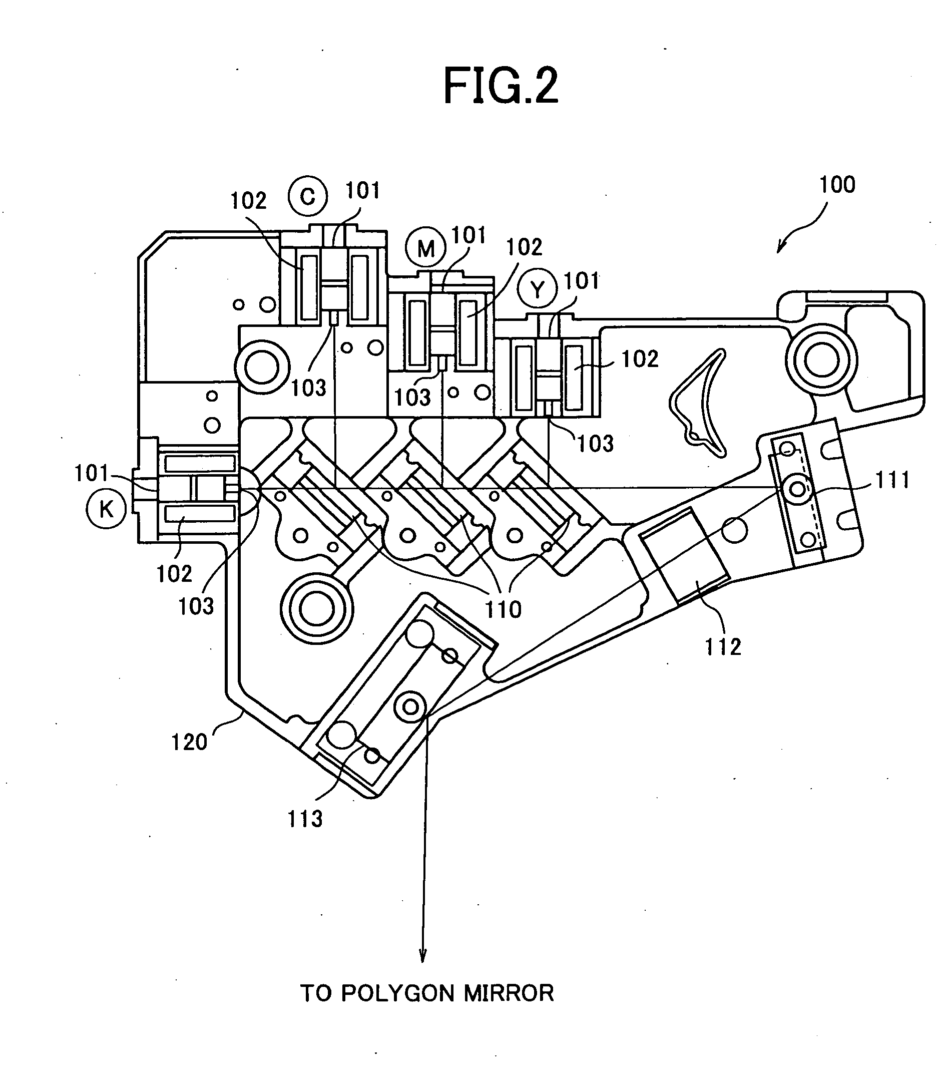
[0018] Another object of the present invention is to provide the optical scanning unit wherein the primary optical system unit and / or the secondary optical system unit include(s) a positioning mechanism for changing the installation positions of the optical elements for reassembling depending on the performance of an image forming apparatus and wherein when the optical elements are reassembled, unnecessary optical elements can be removed to dispose necessary optical elements at the positioning mechanism.

Problems solved by technology

On the other hand, since scanning optical systems corresponding to a plurality of photoreceptors are necessary, a unit for exposing the photoreceptors tends to be large in size and the challenge is to miniaturize the unit.
Another challenge is to eliminate color drift when the toner image developed on each photoreceptor is transferred to the recording paper in an overlapping manner.
However, conventionally, an optical scanning unit has not been proposed which facilitates the highly accurate installation to an image forming apparatus or which facilitates the highly accurate replacement of the optical element, change in the optical path, etc. in preparation for the specification changes such as the speeding up as described above.

Method used


Image

  • Optical scanning unit and image forming apparatus
  • Optical scanning unit and image forming apparatus
  • Optical scanning unit and image forming apparatus

Examples


Embodiment Construction

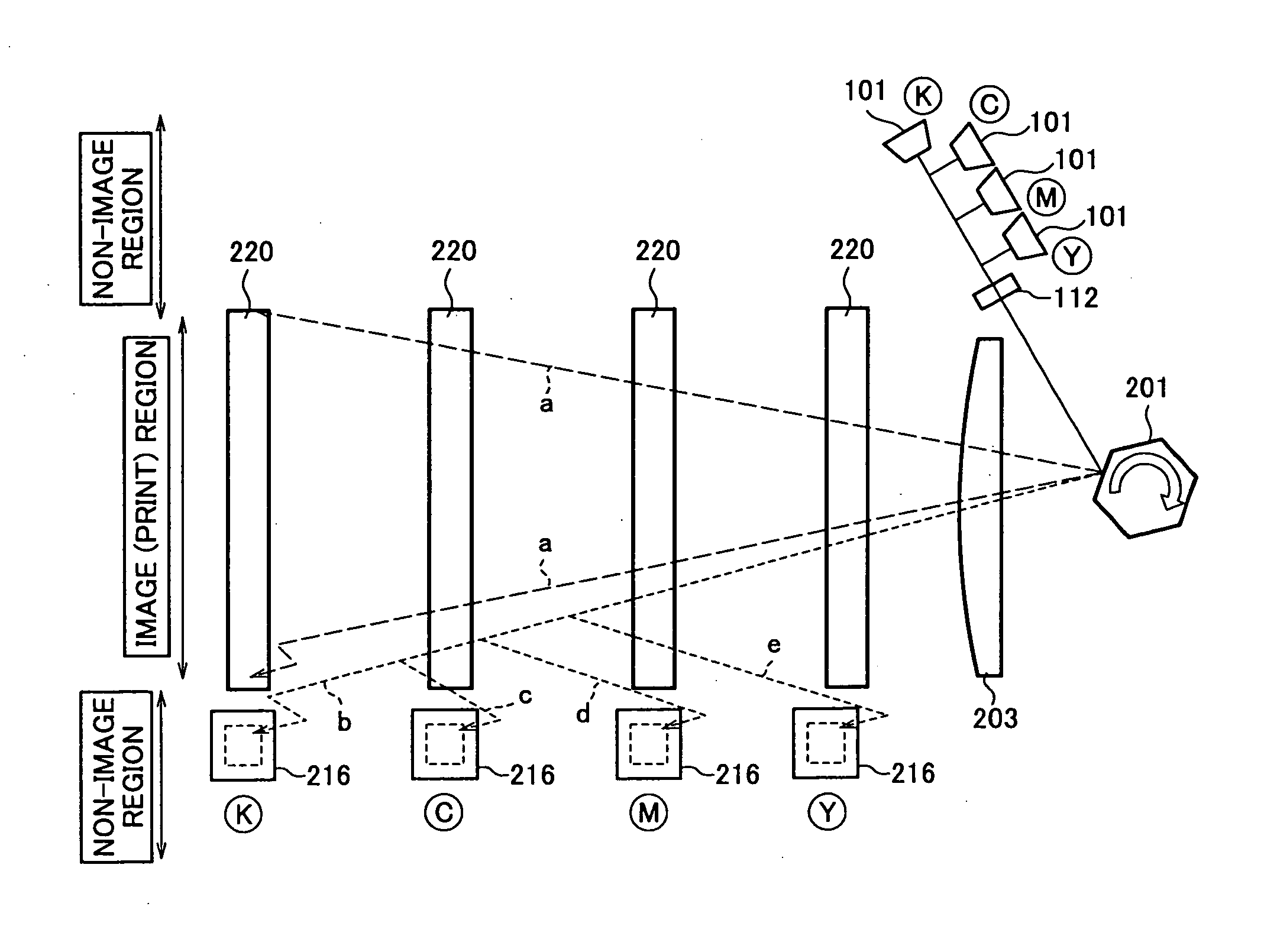
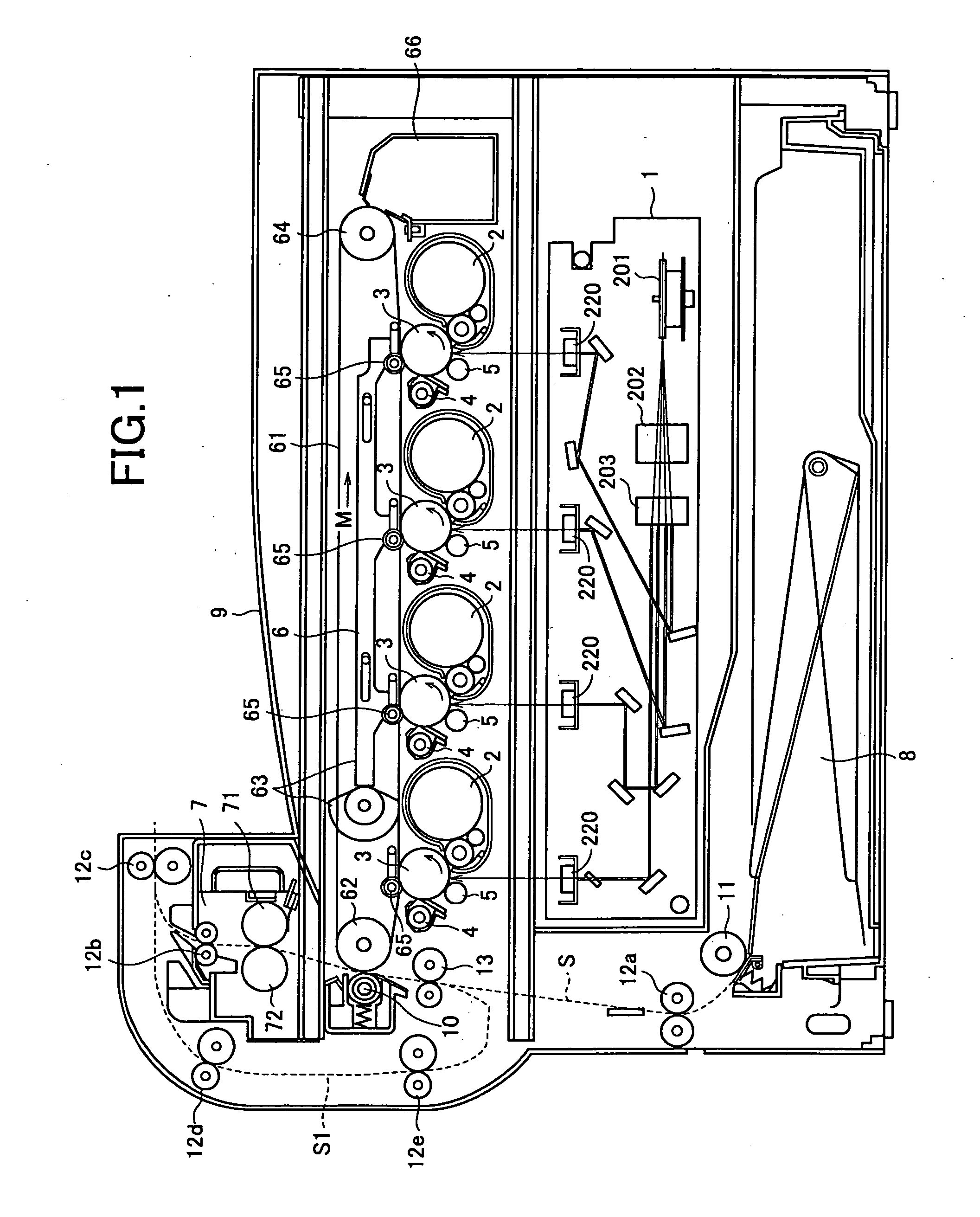
[0040]FIG. 1 shows a configuration example of an image forming apparatus using an optical scanning unit of the present invention. The image forming apparatus forms a multicolor or monochrome image on a predetermined sheet (recording paper) depending on image data transmitted from outside. As shown in FIG. 1, the image forming apparatus is constituted by an exposure unit 1, development units 2, photoreceptor drums 3, cleaner units 4, charging units 5, an intermediate transfer belt unit 6, a fixing unit 7, a paper feeding cassette 8, a paper ejection tray 9, etc.

[0041] The image data handled in the image forming apparatus correspond to a color image using colors of black (K), cyan (C), magenta (M), and yellow (Y). Therefore, four sets of the development units 2, the photoreceptor drums 3, the charging units 5, and the cleaner units 4 are provided such that four types of latent images according to respective four colors are formed and each set is set to black, cyan, magenta, or yellow...


PUM


Abstract

An optical scanning unit irradiates a polygon mirror with a plurality of light beams emitted from a light source according to image data, and scans and exposes a plurality of photoreceptors with the plurality of light beams as scanning lights. The optical scanning unit comprises a primary optical system unit including an optical system that emits the plurality of light beams, which are emitted from the light source toward the polygon mirror, and a secondary optical system unit including an optical system that emits the light beams, which are reflected by the polygon mirror toward the photoreceptors. The arrangement is such that the primary optical system unit is fitted removably to the secondary optical system unit, and that a combined unit of the primary optical system unit and the secondary optical system unit is removably fitted to an image forming apparatus having the photoreceptors.

Description

CROSS-NOTING PARAGRAPH [0001] This non-provisional application claims priority under 35 U.S.C. §119(a) on Patent Application No. 2005-146553 filed in JAPAN on May 19, 2005, the entire contents of which are hereby incorporated herein by reference. FIELD OF THE INVENTION [0002] The present invention relates generally to an optical scanning unit and an image forming apparatus equipped with the optical scanning unit, and, more particularly, to an optical scanning unit used for electrophotographic image forming apparatuses such as digital copy machines, printers, and facsimile machines, for example. BACKGROUND OF THE INVENTION [0003] Image forming apparatuses such as digital copy machines, laser printers, or facsimile machines are widely used. Such an image forming apparatus uses an optical scanning unit that scans a laser beam. When an image is formed in the image forming apparatus, after a photoreceptor is charged by a charging unit, an electrostatic latent image is formed on the photo...

Claims


Application Information

Patent Timeline
IPC IPC(8): B41J2/435
CPCG03G15/0435H04N1/506H04N1/00538G03G2215/0119
Inventor WADA, TAKASUMIOHNO, TAKAYUKIONO, YASUHIROODA, AYUMUNARIKIYO, TAKAHISA
Owner SHARP KK
Learn More