Vector calibration system

a calibration system and vector technology, applied in the field of vector calibration systems, can solve the problems of difficult to determine with enough precision, limited precision to which such systems can correct mismatches, etc., and achieve the effects of improving performance, improving accuracy and efficiency, and improving accuracy of mismatch determination

Inactive Publication Date: 2006-11-23
GREEN ROGER A +4
View PDF63 Cites 19 Cited by
  • Summary
  • Abstract
  • Description
  • Claims
  • Application Information

AI Technical Summary

Benefits of technology

[0006] According to various aspects and methods of the present invention, a signal processing system determines vector mismatch between a plurality of signal paths. Advantageously, such a system can determine mismatch across a range of frequencies. A signal generator can provide a periodic calibration signal having a plurality of frequency components. The system frequency translates the calibration signal to provide a first set of observed samples. The first sample set is compared to a second set of samples, which are modeled by a function of parameters including an estimated vector mismatch and a plurality of basis functions. A value of vector mismatch is determined (at least to an estimate) that minimizes the difference between the first sample set and the second sample set.
[0007] According to one advantageous aspect of the invention, the calibration signal comprises multiple tones having predetermined gain, phase and frequency relationships to each other. By providing a periodic calibration signal with a plurality of tones, the signal processing system is able to concurrently determine vector mismatch at the frequency of each tone. Consequently, the system can determine mismatch across a range of frequencies simply and efficiently.
[0008] By minimizing the difference between a set of observed samples and a set of samples modeled by basis functions, the system can determine vector mismatch using linear techniques. According to various advantageous aspects of the invention, deterministic least squares can be employed. Straightforward and efficient recursive techniques such as least mean squares (LMS) and recursive (i.e., adaptive) least squares (RLS) can also be employed.
[0011] A system according to still another advantageous aspect of the present invention provides a plurality of first sample sets. The system determines, at least to an estimate, a plurality of vector mismatch values by comparing each respective first sample set to a respective second sample set modeled by basis functions and minimizing the difference between the compared sample sets. By statistically combining the values of vector mismatch determined for each one of the plurality of first sample sets, such a system can improve accuracy of the mismatch determination while keeping the interval of each sample set relatively short. Sample sets having shorter intervals are less prone to problems caused by local-oscillator induced phase variation between the frequency-translated calibration signal and the basis functions.
[0012] Quadrature receiver and array processor systems operating in accordance with further aspects of the invention determine and correct vector mismatch across a range of frequencies, thus providing improved performance. Vector mismatch between in-phase and quadrature signal paths can be more accurately and efficiently determined and corrected across a range of frequencies to improve demodulator performance or image rejection. Similarly, vector mismatch between array elements can be better determined and corrected to improve array efficiency and sidelobe rejection.

Problems solved by technology

The precision to which such systems can correct mismatch is limited, however, because the mismatch often varies with frequency and is difficult to determine with enough precision to achieve high separation between desired and undesired signals.

Method used


Image

  • Vector calibration system
  • Vector calibration system
  • Vector calibration system

Examples


Embodiment Construction

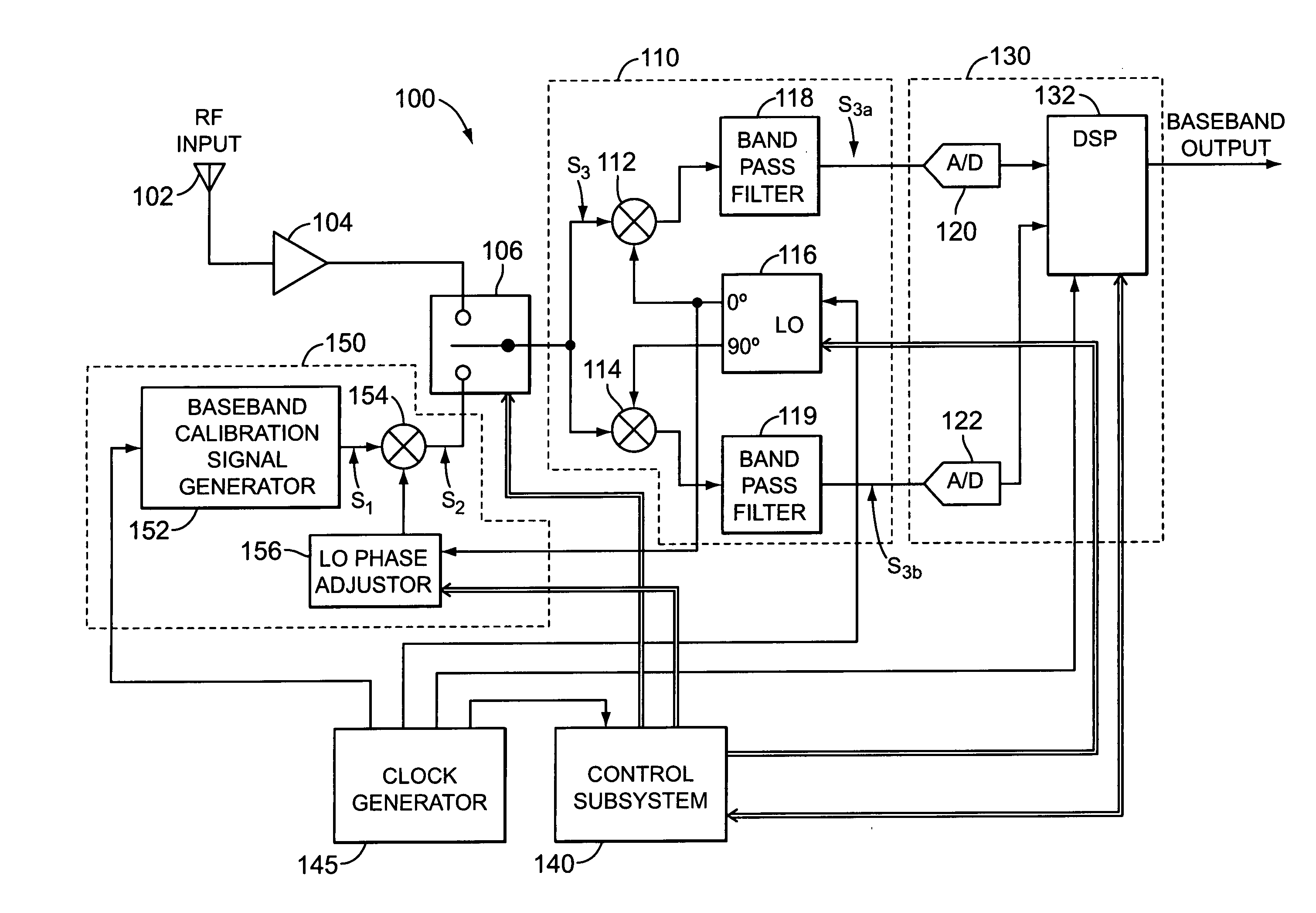
[0031] A vector calibration system according to various aspects of the present invention provides numerous benefits, including concurrently determining vector mismatch between a plurality of signal paths across a range of frequencies. Such a system can be advantageously implemented in any communication system that separates signals using a plurality of signal paths having a predetermined vector relationship. As may be better understood with reference to FIG. 1, for example, a low-IF receiver 100 employs quadrature signal paths to separate desired signals from image signals having opposite frequencies. Conventional low-IF (low intermediate frequency) receivers reduce the complexity of IF processing by performing the processing at frequencies that are much closer to the baseband frequency range of a signal of interest than the RF frequency of the signal. In a receiver variation having circuitry similar to that of receiver 100, quadrature signal paths are employed to separate frequency...


PUM


Abstract

Among other things, calibration of a signal processing system is disclosed to minimize vector mismatch between signals frequency-translated from an RF signal and conveyed along a plurality of signal paths of the signal processing system. A calibration signal having a plurality of tones is coupled to the signal processing system such that it is frequency translated. The frequency-translated calibration signal is sampled along a first signal path of the signal processing system to obtain a first set of observed samples. It is also sampled along a second signal path of the system to obtain a second set of observed samples. The first set of observed samples is filtered with an adaptive filter having a set of adaptable coefficients to obtain a set of filtered samples. The coefficients are adapted to minimize undesired deviations between the set of filtered samples and the second set of observed samples.

Description

CROSS-REFERENCE TO RELATED APPLICATIONS [0001] This application is a continuation of U.S. application Ser. No. 09 / 730,681, filed on Dec. 6, 2000, which claims benefit of U.S. Provisional Application No. 60 / 190,226, filed Mar. 15, 2000. Both of those applications are incorporated herein by reference, and all U.S. patents or patent applications, published or appended articles, and any other written materials incorporated by reference therein are also specifically incorporated herein by reference.BACKGROUND OF THE INVENTION [0002] Communication systems frequently separate signals by using a plurality of signal paths that have a predetermined vector relationship. By suitably combining the signal paths, such systems can cancel out undesired signals by mathematically exploiting predetermined phase and amplitude relationships between respective signal vectors of each signal path. [0003] Quadrature image rejection receivers employ signal paths having a quadrature relationship to discriminat...

Claims


Application Information

Patent Timeline
Patent Type & Authority Applications(United States)
IPC IPC(8): H04K1/10H04B1/10H04B17/40
CPCH04L27/364
Inventor GREEN, ROGER A.FARDEN, DAVID C.PIERRE, JOHN W.ANDERSON-SPRECHER, RICHARD C.SUOMINEN, EDWIN A.
Owner GREEN ROGER A
Why Eureka
Try Eureka