Nanofiber Mats and production methods thereof

Active Publication Date: 2006-11-23
RES TRIANGLE INST
View PDF62 Cites 116 Cited by
  • Summary
  • Abstract
  • Description
  • Claims
  • Application Information

AI Technical Summary

Benefits of technology

[0018] According to a third aspect of the present invention, there is provided a novel mat of fibers, the mat having a plurality of first and second fibers intermixed therein; having a cross section fiber d

Problems solved by technology

However, fibers produced from the apparatus in FIG. 1 can suffer from poor adherence among the fibers that constitute the fiber mat due to the electrospun substances havin

Method used


Image

  • Nanofiber Mats and production methods thereof
  • Nanofiber Mats and production methods thereof
  • Nanofiber Mats and production methods thereof

Examples


example i

[0064] a poly(ethylenimine) solution of a molecular weight of 1050 kg / mol for the first fibers and a poly(caprolactone) solution of a molecular weight of 100 kg / mol for the second fibers,

[0065] a solvent of dimethylformamide (DMF) for both the first and second fibers,

[0066] extrusion elements tip diameter of 1000 μm for both fibers,

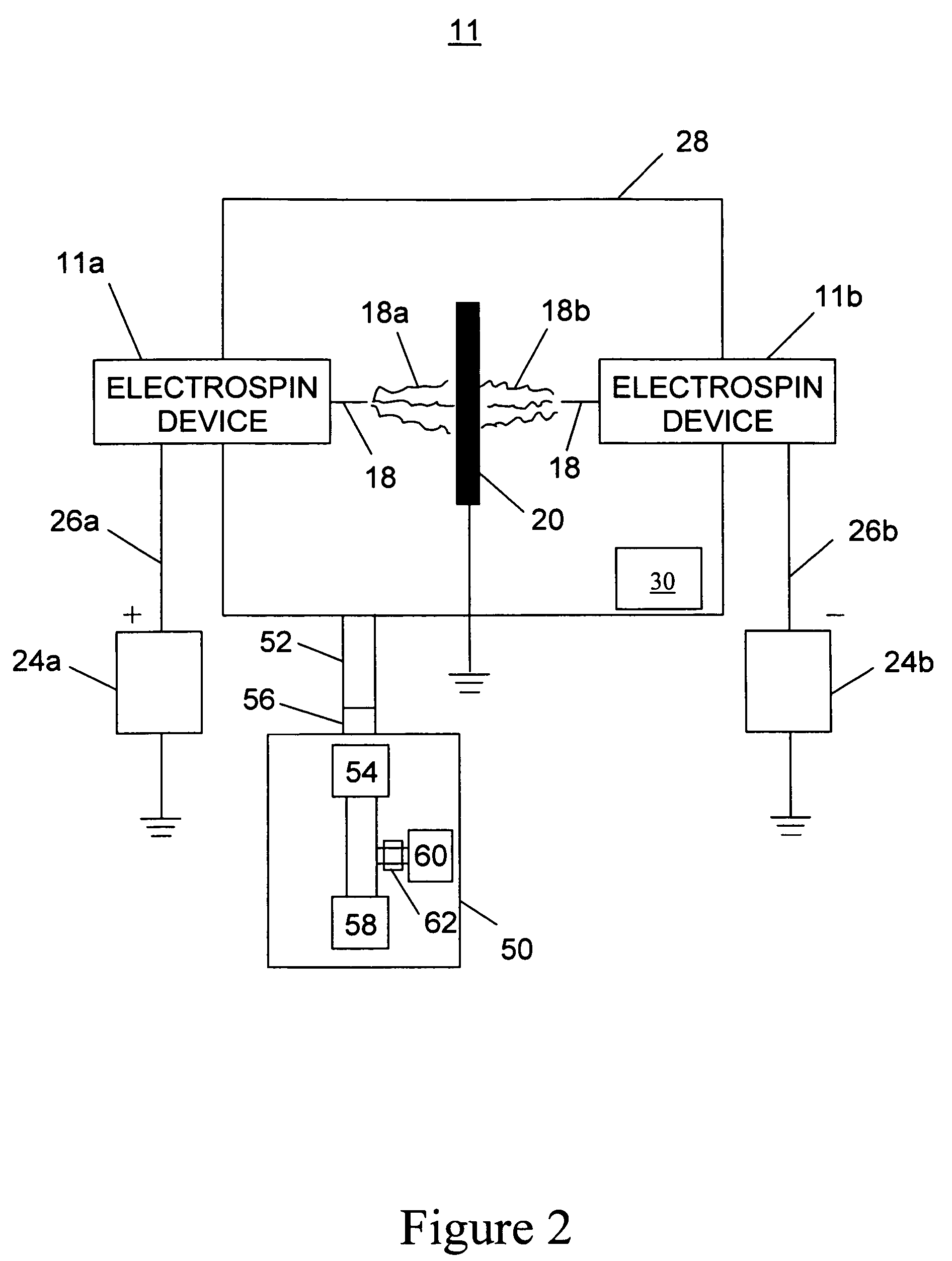
[0067] an Al ring collector,

[0068] 0.5 to 1.0 ml / hr pump rate providing the polymer solution to the extrusion elements, a gas flow rate in the range of 0.5 to 50 lpm,

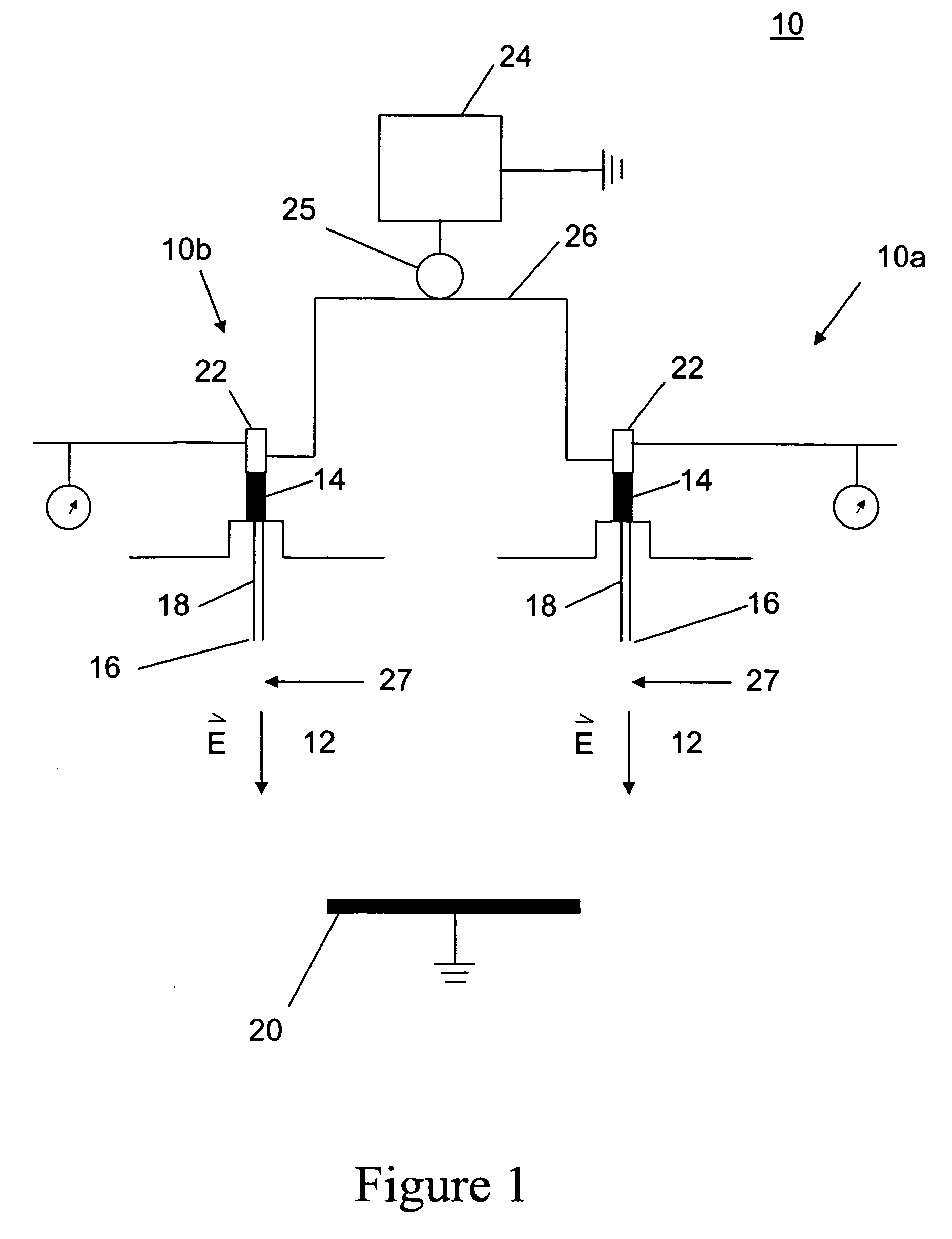
[0069] an electric field strength of 2 kV / cm for electrospinning the first and second fibers, positive polarity for the first fibers and negative polarity for the second fibers, and

[0070] a gap distance between the tip of the extrusion elements and the collector of 17.5 cm.

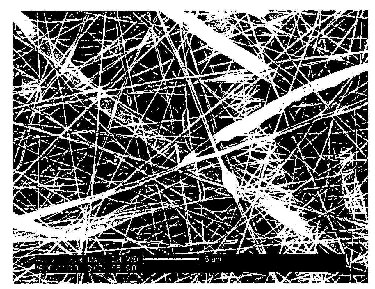
[0071] Using the above substances for electrospinning and the above conditions, a mat having the first fibers made of a material different than the second fibers is obtained. The resultant fiber diameter depends on s...

example ii

[0072] a polystyrene solution of a molecular weight of 1050 kg / mol for the first fibers and a polystyrene solution of a molecular weight of 2000 kg / mol for the second fibers,

[0073] a solvent of dimethylformamide DMF for both the first and second fibers,

[0074] extrusion elements tip diameter of 1000 μm for both fibers,

[0075] an Al ring collector,

[0076] 0.5 to 1.0 ml / hr pump rate providing the polymer solution to the extrusion elements,

[0077] a gas flow rate in the range of 0.5 to 50 lpm

[0078] an electric field strength of 2 kV / cm for the first fibers,

[0079] an electric field strength of 5 kV / cm for the second fibers,

[0080] positive polarity for the first fibers and negative polarity for the second fibers, and

[0081] a gap distance between the tip of the extrusion elements and the collector of 17.5 cm.

[0082] The resultant fiber mat includes first fibers with a first average diameter and second fibers with a second average diameter, different than the first average diameter. I...


PUM

PropertyMeasurementUnit
Lengthaaaaaaaaaa
Fractionaaaaaaaaaa
Percent by massaaaaaaaaaa

Abstract

An apparatus and method in which the apparatus includes a first electrospinning device configured to electrospin first fibers of a first substance, a second electrospinning device configured to electrospin second fibers of a second substance such that first and second fibers combine in a mat formation region, and a biasing device configured to bias the first electrospinning device with a first electric polarity and to bias the second electrospinning device with a second electric polarity of opposite polarity to the first electric polarity to promote attraction and coalescence between the first and second fibers. The method electrospins under the first electric polarity first fibers from the first substance, electrospins under the second electric polarity fibers from the second substance, and coalesces the first and second fibers to form the fiber mat.

Description

CROSS-REFERENCE TO RELATED APPLICATIONS [0001] This application is related to U.S. Pat. No. XXXXXXXX, filed as U.S. application Ser. No. 10 / 819,942, on Apr. 8, 2004, entitled “Electrospray / Electrospinning Apparatus and Method,” Attorney Docket No. 241013US-2025-2025-20, the entire contents of which are incorporated herein by reference. This application is related to U.S. Pat. No. YYYYYYYY, filed as U.S. application Ser. No. 10 / 819,945, on Apr. 8, 2004, entitled “Electrospinning in a Controlled Gaseous Environment,” Attorney Docket No. 245016US-2025-2025-20, the entire contents of which are incorporated herein by reference. This application is related to U.S. Pat. No. ZZZZZZZZ, filed as U.S. application Ser. No. 10 / 819,916, on Apr. 8, 2004, entitled “Electrospinning of Fibers Using a Rotating Spray Head,” Attorney Docket No. 245015US-2025-2025-20, the entire contents of which are incorporated herein by reference.BACKGROUND OF THE INVENTION [0002] 1. Field of the Invention [0003] This...

Claims


Application Information

Patent Timeline
IPC IPC(8): D04H1/00
CPCD01D5/0061D04H1/42Y10T428/298Y10T428/2913Y10T428/2915Y10T428/29D04H1/4291Y10T442/60Y10T442/614Y10T442/615Y10T442/625Y10T442/626Y10T442/659Y10T442/66Y10T442/681Y10T442/69Y10T442/692Y10T442/696Y10T442/697Y10T442/699
Inventor ANDRADY, ANTHONY L.ENSOR, DAVID S.WALKER, TERI A.PRABHU, PURVA
Owner RES TRIANGLE INST
Why Eureka
Try Eureka