Posterior spinal arthroplasty-development of a new posteriorly inserted artificial disc, a new anteriorly inserted artifical disc and an artificial facet joint

a technology of anteriorly inserted artifical discs, applied in the field of posterior spinal arthroplasty, can solve the problems of physiological stop to further extension, and achieve the effect of reducing the strain on adjacent discs, reducing the risks of adjacent segment disc failure, and overcompensating problems and disadvantages

Inactive Publication Date: 2006-11-23
SPINADYNE
View PDF99 Cites 154 Cited by
  • Summary
  • Abstract
  • Description
  • Claims
  • Application Information

AI Technical Summary

Benefits of technology

[0096] Thus, the present invention overcomes the problems and disadvantages associated with current disc replacement strategies. It has all the benefits associated with posterior lumbar inter-body fusion surgery, but at the same time it allows movement at that le...

Problems solved by technology

This results in a physiolo...

Method used


Image

  • Posterior spinal arthroplasty-development of a new posteriorly inserted artificial disc, a new anteriorly inserted artifical disc and an artificial facet joint
  • Posterior spinal arthroplasty-development of a new posteriorly inserted artificial disc, a new anteriorly inserted artifical disc and an artificial facet joint
  • Posterior spinal arthroplasty-development of a new posteriorly inserted artificial disc, a new anteriorly inserted artifical disc and an artificial facet joint

Examples


Embodiment Construction

Lumbar Disc Prosthesis for Insertion Via a Posterior Route

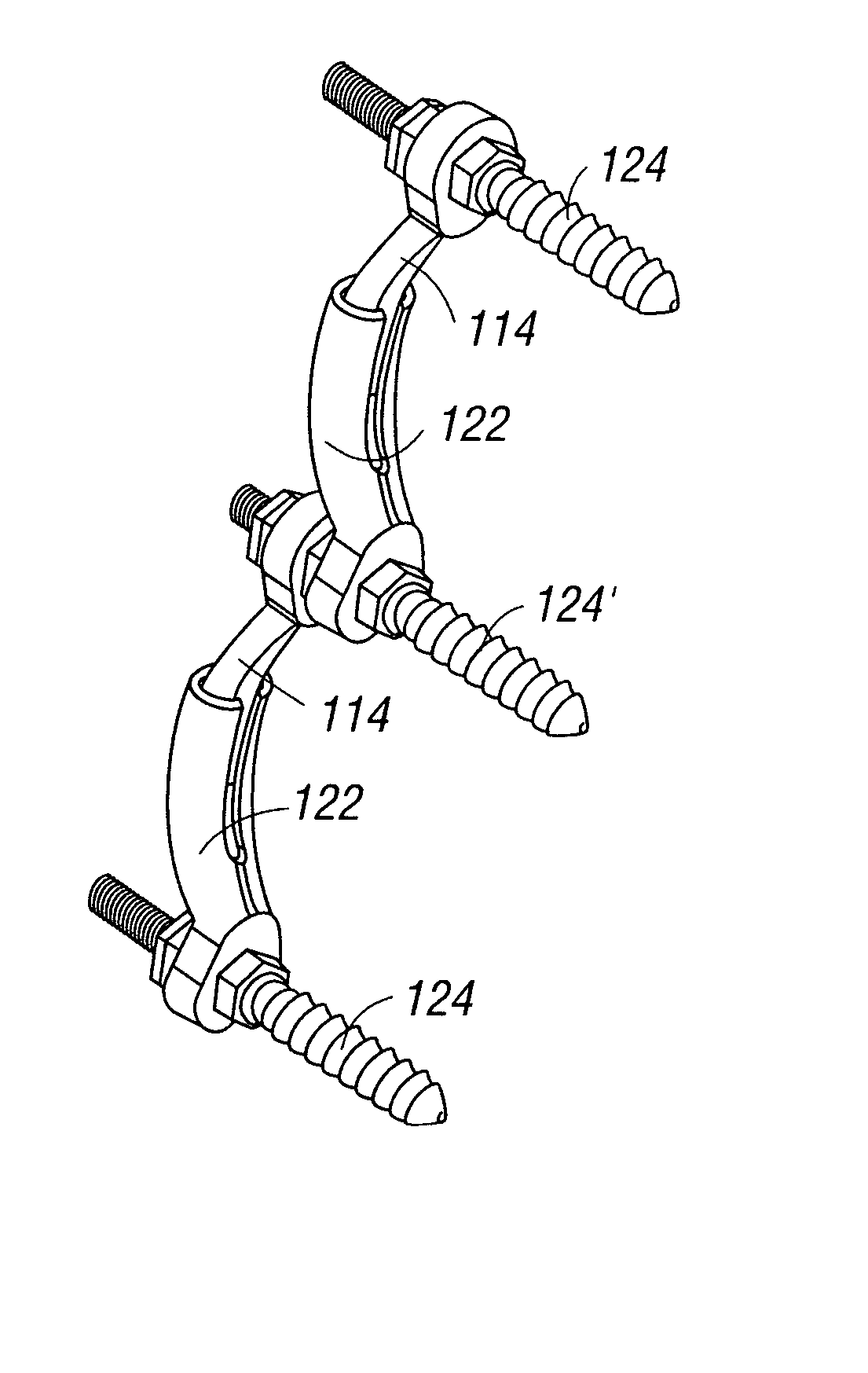
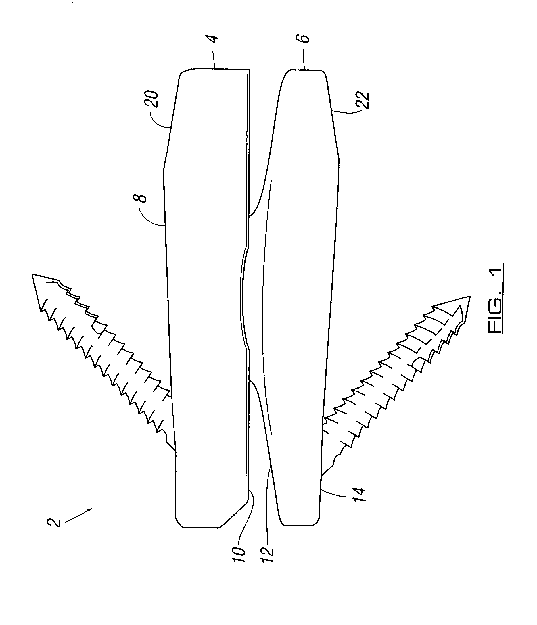
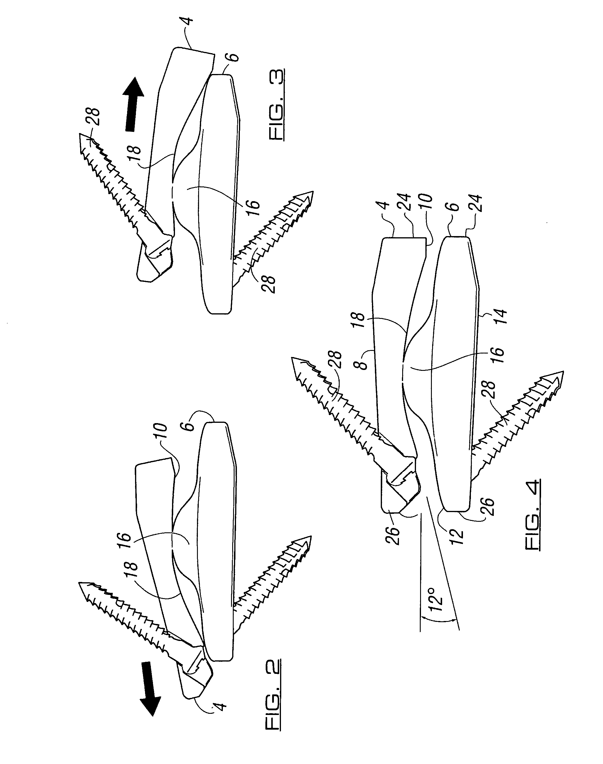
[0141] Referring firstly to FIGS. 1-30, there is illustrated a lumbar disc prosthesis 2 which can be inserted into a lumbar disc space via a posterior route as a replacement for a diseased and / or damaged lumbar disc.

[0142] The disc prosthesis 2 includes two pairs of disc members, each pair including an upper disc member 4, 4′ and a lower disc member 6, 6′. (Use of a reference numeral with ′ thereafter refers to a second or further feature equivalent to the feature indicated by the reference numeral alone. Thus, disc member 4 refers to the first prosthesis pair upper member and disc member 4′ refers to the second prosthesis pair upper member). The upper and lower disc members 4, 6; 4′, 6′ of each pair constitute a left and right disc prosthesis respectively. These disc members are shaped and dimensioned such that they can be inserted into a lumbar disc space either side of the dural sac whilst taking into account the poster...


PUM

PropertyMeasurementUnit
Fractionaaaaaaaaaa
Lengthaaaaaaaaaa
Thicknessaaaaaaaaaa

Abstract

A lumbar disc prosthesis is provided including a pair of disc members. The first member of the disc pair has a vertebral disc contact surface and a recessed portion on an opposing surface thereof. The second member of the disc pair has a vertebral disc contact surface and a protruding portion on an opposing surface thereof. The protruding portion of the second member engages with the recessed portion of the first member in use. Each of the first and second disc members are provided with at least three sections; a middle section and two end sections. The recessed and protruding portions are provided in the middle section of the respective disc members and each of the two end sections have a narrowing taper towards the ends of the disc members. The facet joint prosthesis includes a first member for attachment to a first posterior lumbar disc in use and a second member for attachment to a second posterior lumbar disc in use. At least a part of the first member is telescopically mounted in at least a part of the second member in use.

Description

REFERENCE TO PENDING APPLICATIONS [0001] This application is a continuation-in-part of pending U.S. application Ser. No. 11 / 203,259 filed on Aug. 12, 2005, which is a continuation-in-part of pending U.S. Application No. 10 / 970,091 filed on Oct. 21, 2004.FIELD OF THE INVENTION [0002] This invention relates to devices and surgical methods for the treatment of various types of spine pathologies. It deals with the development of an artificial facet joint, and an artificial lumbar disc replacement that is specifically designed to be inserted from a posterior approach to the spine. It also deals with the development of an artificial disc replacement that can be inserted from an anterior approach to the spine. BACKGROUND OF THE INVENTION [0003] Back pain affects 40% of the population. Up to 20% of the population visit their family doctor requesting help with their back problem. Up to 30% of patients continue to complain of significant back pain at one year following the onset of their symp...

Claims


Application Information

Patent Timeline
IPC IPC(8): A61F2/44A61B17/70
CPCA61B17/7007A61F2310/00796A61B17/7013A61B17/7014A61B17/7019A61B17/7059A61B17/7064A61F2/30771A61F2/4405A61F2/4425A61F2/4611A61F2002/30112A61F2002/30156A61F2002/30286A61F2002/30331A61F2002/30367A61F2002/30369A61F2002/3037A61F2002/30372A61F2002/30373A61F2002/30495A61F2002/30507A61F2002/30578A61F2002/30601A61F2002/3065A61F2002/30654A61F2002/30828A61F2002/30841A61F2002/30884A61F2002/30934A61F2002/448A61F2002/449A61F2220/0025A61F2220/0033A61F2230/0004A61F2230/0023A61F2230/0063A61F2310/00017A61F2310/00023A61F2310/00179A61B17/7011
Inventor KRISHNA, MANOJFRIESEM, TAI
Owner SPINADYNE
Why Eureka
Try Eureka