Thermoacoustic Thermomagnetic Generator

Inactive Publication Date: 2006-11-30
FELLOWS OSCAR L
View PDF8 Cites 20 Cited by
  • Summary
  • Abstract
  • Description
  • Claims
  • Application Information

AI Technical Summary

Problems solved by technology

The application of heat causes the keeper to transition between magnetic and non-magnetic states, and temporarily lose its ability to conduct magnetic lines of force, thereby opening the magnetic circuit.

Method used


Image

  • Thermoacoustic Thermomagnetic Generator
  • Thermoacoustic Thermomagnetic Generator
  • Thermoacoustic Thermomagnetic Generator

Examples


Embodiment Construction

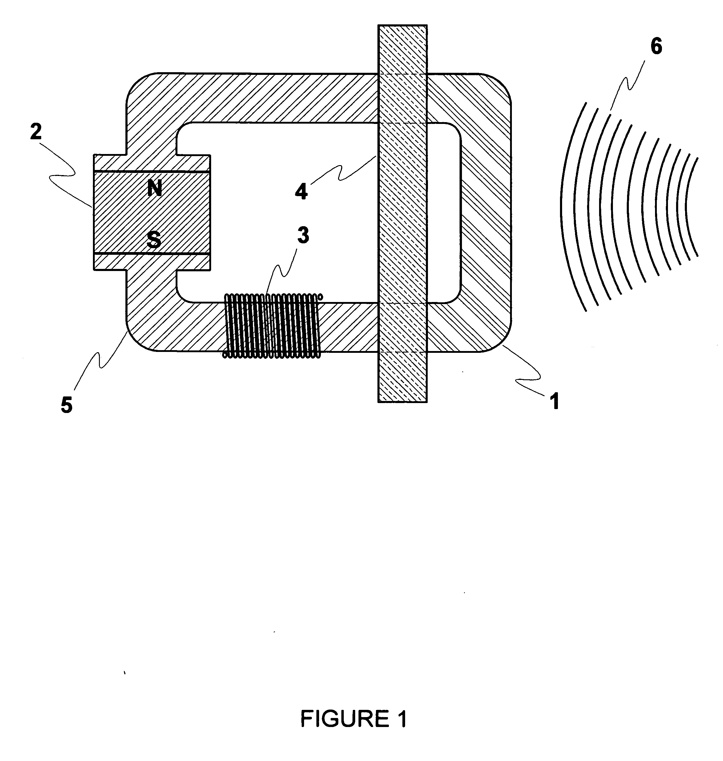
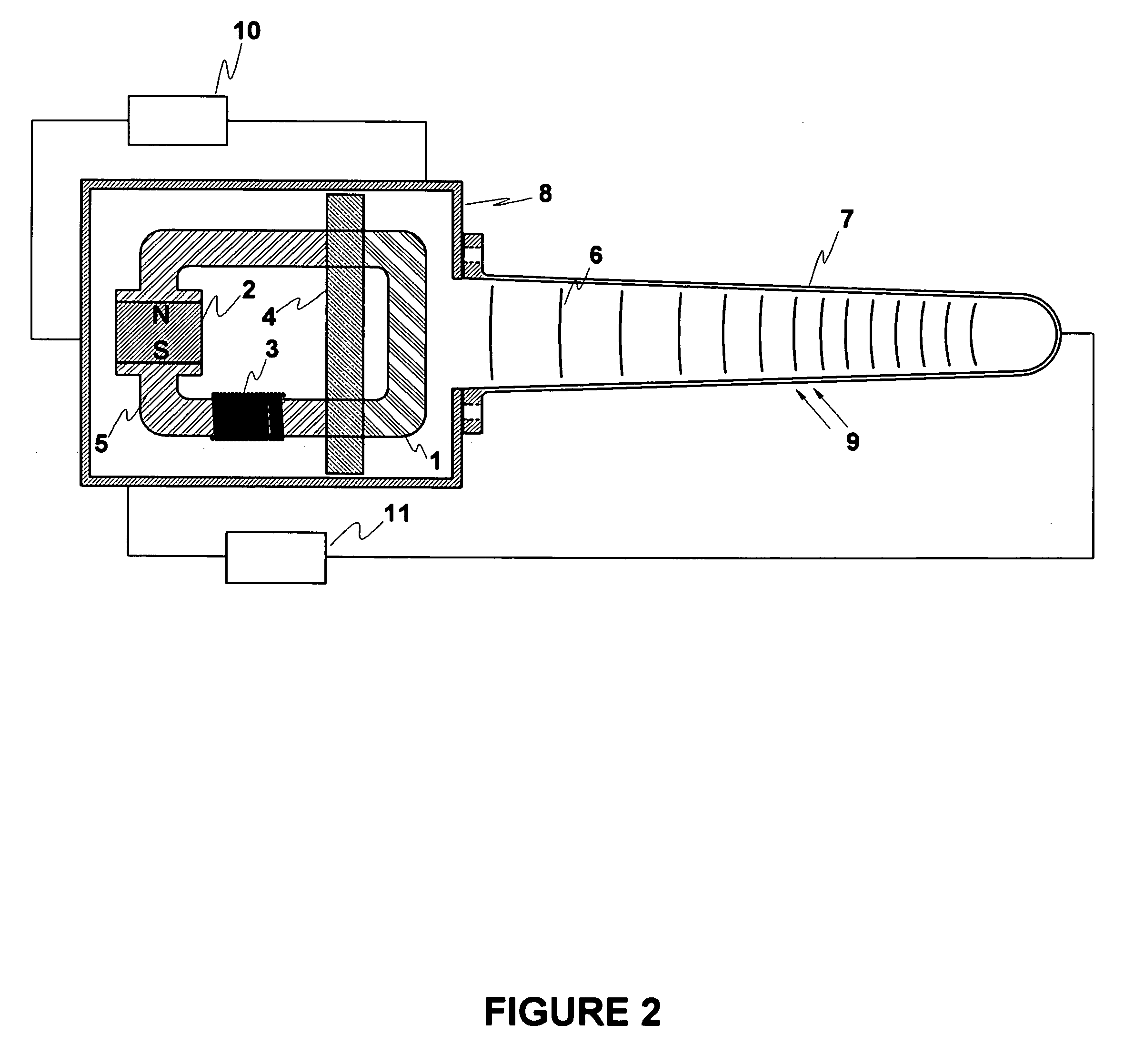
[0037] The Thermoacoustic Thermomagnetic Generator will be described with reference to drawings that are not to scale.

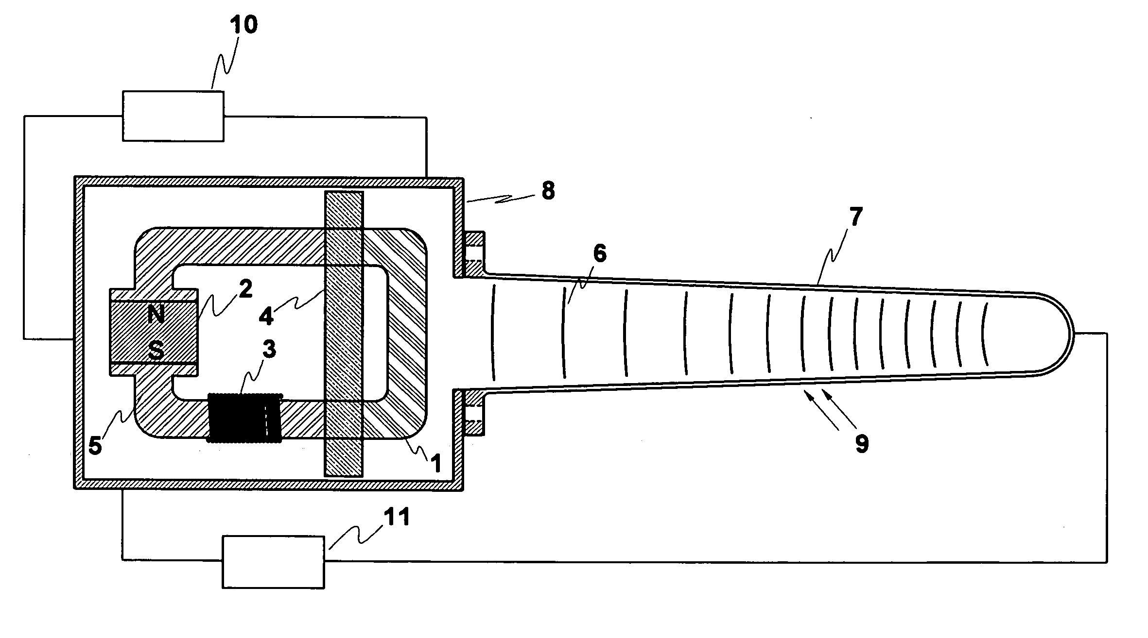
[0038] With reference to FIG. 1, the magnetic circuit opening and closing means 1 is in fixed contact with the stator means 5 and completes the magnetic circuit path with the poles of the magnetic field generating means 2. The thermal insulating means 4 is formed around the ends of the stator means 5 and the magnetic circuit opening and closing means 1 near where they are joined. The induction windings 3 are wound around the stator means pole piece. The thermoacoustic waves 6 impinge upon the magnetic circuit opening and closing means 1, periodically heating it past its Curie point and opening the magnetic circuit so that the magnetic field collapses and induces an electric current in the induction windings 3. The magnetic circuit opening and closing means 1 cools during the period between the thermoacoustic waves 6 and re-establishes the magnetic field. The expandi...


PUM


Abstract

This Thermoacoustic Thermomagnetic Generator uses the thermal gradient in thermoacoustic waves to periodically raise the temperature of a thermomagnetic material past its Curie point so that it alternates between magnetic and non-magnetic states. In conjunction with a stator, induction windings and magnet, the metal alloy forms a magnetic circuit that is periodically interrupted and re-established by the action of the thermoacoustic waves. The expanding and collapsing magnetic field induces an alternating current in the stator windings. The resultant generator has no moving parts. This Thermoacoustic Thermomagnetic Generator embodies hot and cold heat exchangers, a working fluid contained in a reservoir that is divided into hot and cold zones, a resonant waveguide means and an electrical generating means that are typical of the art of thermoacoustic engine-generators, but the thermal-to-electric conversion means and process are entirely unique. This basic arrangement of components can be scaled in size from the micro-miniature to the very large. The thermoacoustic thermomagnetic generators can also be arrayed in multiple units with common waveguide, housing and hot and cold heat exchanger means, such as in a panel array of multiple miniature units.

Description

BACKGROUND OF THE INVENTION [0001] The first record known to this inventor, of a thermo-magnetic motor making use of the Curie point property of materials, is the Nikola Tesla patent of 1886, U.S. Pat. No. 396,121. In his patent Dr. Tesla describes a kinematic thermo-magnetic motor in which a mechanism is caused to reciprocate by means of interrupting a magnetic circuit by the periodic application of heat to a metal “keeper” component that completes the magnetic circuit. The application of heat causes the keeper to transition between magnetic and non-magnetic states, and temporarily lose its ability to conduct magnetic lines of force, thereby opening the magnetic circuit. When the heat is removed the keeper cools below the Curie point transition temperature and returns to a ferromagnetic state, and the magnetic circuit is re-established. [0002] The material property that facilitates this application is known today as the Curie point of the material. It is the temperature at which a ...

Claims


Application Information

Patent Timeline
Patent Type & Authority Applications(United States)
IPC IPC(8): F01K13/00
CPCH01L37/04H10N15/20
Inventor FELLOWS, OSCAR L.
Owner FELLOWS OSCAR L
Why Eureka
Try Eureka