Heat dissipation structure of an electronic device

a technology of electronic devices and heat dissipation structures, which is applied in the construction details of electrical apparatuses, instruments, basic electric elements, etc., can solve the problems of large installation space for dust tends to accumulate inside the electronic devices, and the use of electric fans with mini heat sinks or heat pipes requires a lot of installation space in the electronic devices, so as to increase the heat dissipation area

Active Publication Date: 2006-11-30
FIRST INTERNATIONAL COMPUTER
View PDF1 Cites 23 Cited by
  • Summary
  • Abstract
  • Description
  • Claims
  • Application Information

AI Technical Summary

Benefits of technology

[0006] The present invention has been accomplished under the circumstances in view. According to one aspect of the present invention, the heat dissipation structure comprises a housing that has one panel (side) formed of a heat sink for dissipating heat from the active components of the circuit board housed inside the housing. The heat sink has radiation fins perpendicularly protruded from the flat outside wall thereof to increase the heat dissipation area of the heat sink.

Problems solved by technology

However, an electric fan consumes much electric energy, and causes noises during operation.
When a heat pipe is used with an electric fan that causes a convection of air, dust tends to be accumulated inside the electronic device.
Further, the use of an electric fan with a mini heat sink or heat pipe requires much installation space in the electronic device.

Method used


Image

  • Heat dissipation structure of an electronic device
  • Heat dissipation structure of an electronic device
  • Heat dissipation structure of an electronic device

Examples


Embodiment Construction

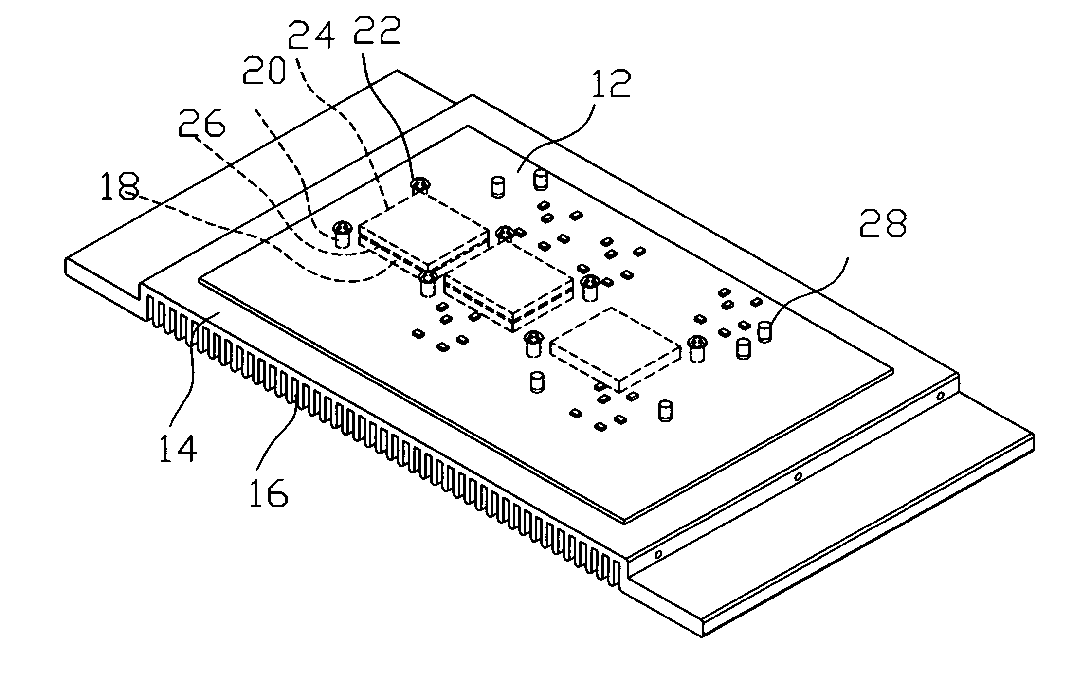
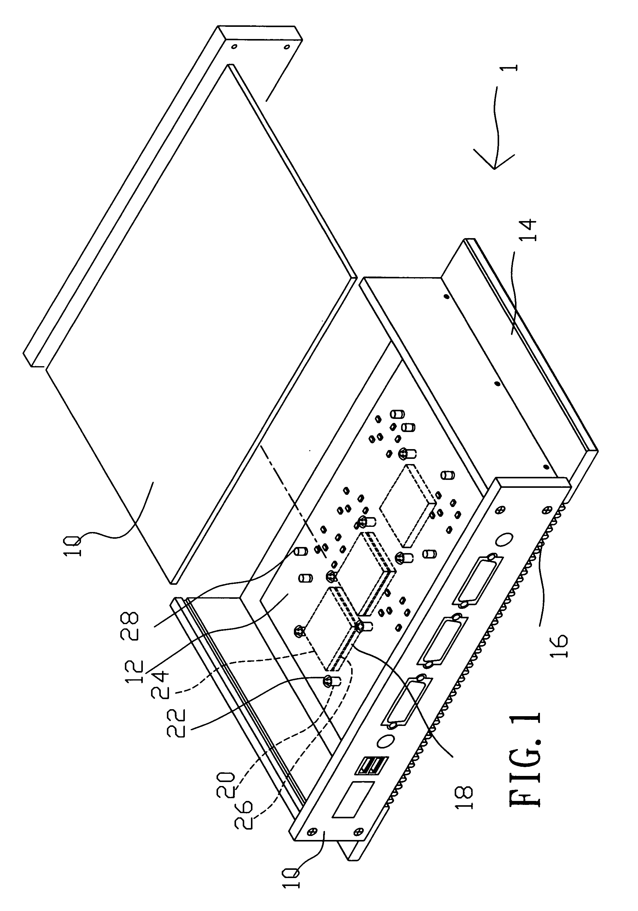
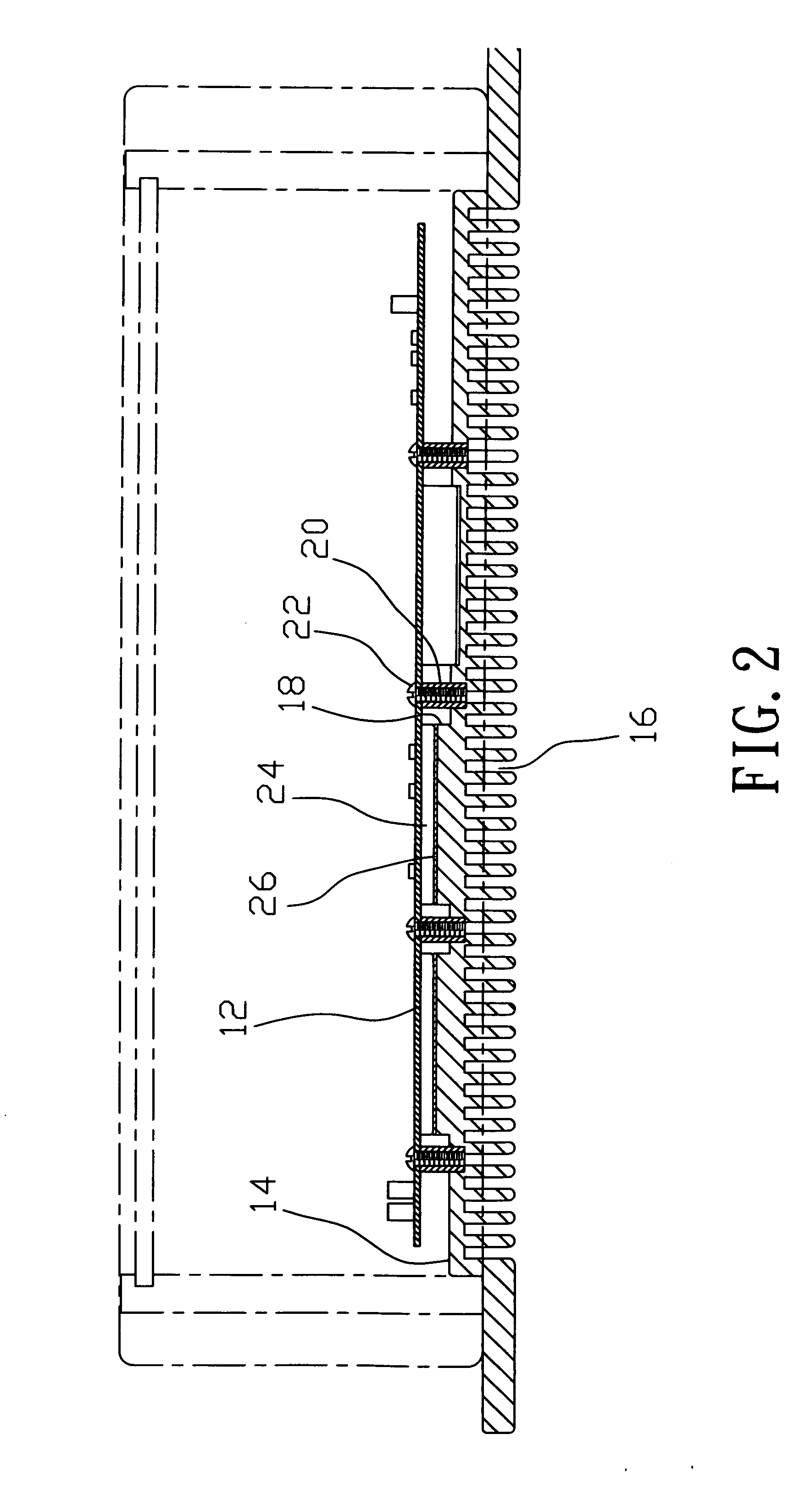
[0014] Referring to FIGS. 1 and 2, a heat dissipation structure 1 in accordance with the present invention is shown used in an electronic device comprising a heat conducting housing 10, which accommodates a circuit board 12. The heat conducting housing 10 has one sidewall formed of a heat sink 14, which supports the circuit board 12 and has upright radiation fins 15 that increase the heat dissipation surface of the heat sink 14. The upright radiation fins 15 are perpendicularly protruded from the flat outside wall of the heat sink 14 and arranged in rows. Further, the housing 10 has at least one communication port and at least one indicator light provided at one side.

[0015] Referring to FIGS. 3 and 4, the circuit board 12 comprises a plurality of active components, for example, three active components 24, and a plurality of passive components 28. The active components 24 are provided at the bottom side of the circuit board 12. The passive components 28 can be provided at the top si...


PUM


Abstract

Disclosed is a heat dissipation structure, which includes a housing that houses a circuit board having active components, a heat sink formed integral with one side of the housing for supporting the circuit board and having radiation fins on the outside, a plurality of heat pads provided at the inside wall of the heat sink corresponding to the active components, and heat conducting bonding layers bonded between the heat pads and the active components for quick dissipation of heat from the active components into the outside open air through the heat pads and the heat sink.

Description

BACKGROUND OF THE INVENTION [0001] 1. Field of the Invention [0002] The present invention relates to an electronic device and more particularly, to a heat dissipation structure of an electronic device, which dissipates heat from the passive components of the electronic device efficiently without the use of an electric fan. [0003] 2. Description of the Related Art [0004] Following fast development of technology, a variety of advanced and sophisticated electronic devices have been created to make our life better. Regular electronic devices may use a number of active components that produce heat during operation. In order to maintain optimum working atmosphere for these active components, heat must be quickly carried away from these active components during working. According to study, the service life of will be shortened by one half when increasing the working temperature by 10° C. Conventionally, electric fans are used with mini heat sinks or heat pipes for carrying heat away from t...

Claims


Application Information

Patent Timeline
Patent Type & Authority Applications(United States)
IPC IPC(8): H01L21/50H01L23/34G06F1/18G06F1/20H05K7/20
CPCG06F1/181H05K7/20445G06F1/20
Inventor CHEN, CHENG TE
Owner FIRST INTERNATIONAL COMPUTER
Why Eureka
Try Eureka