

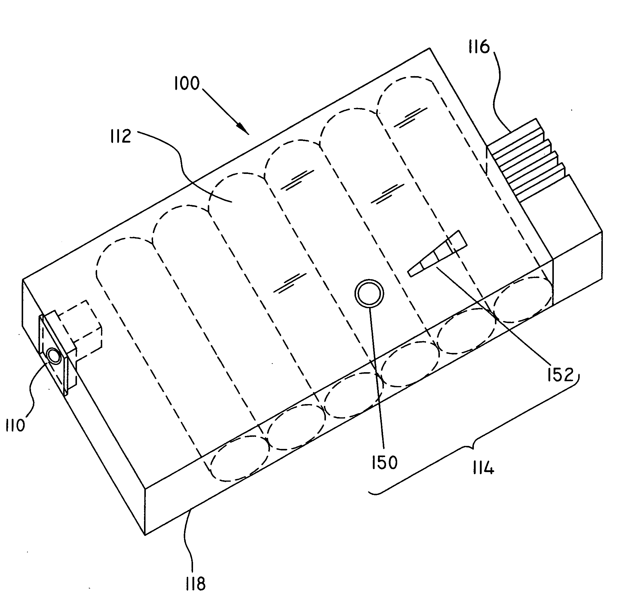
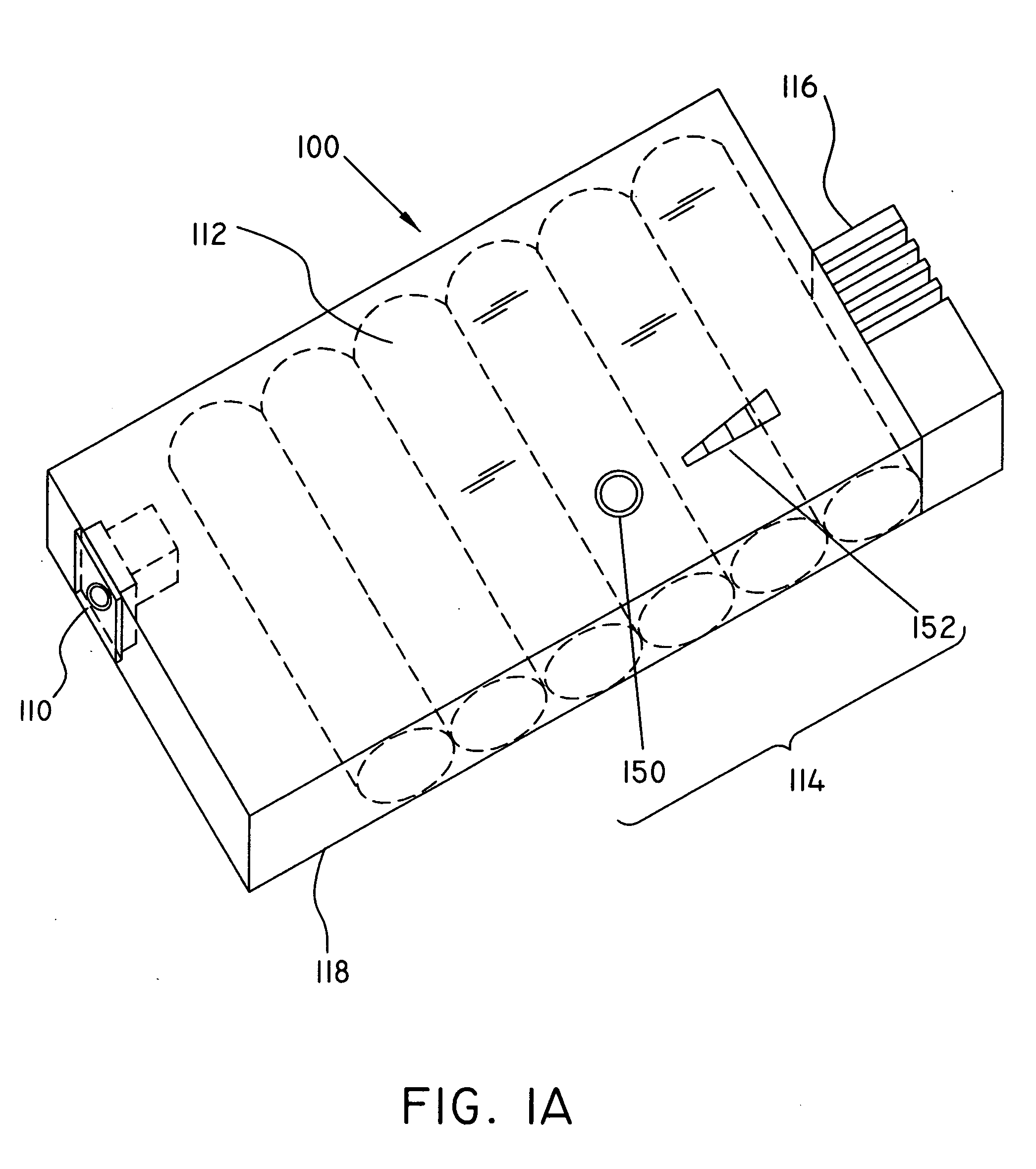
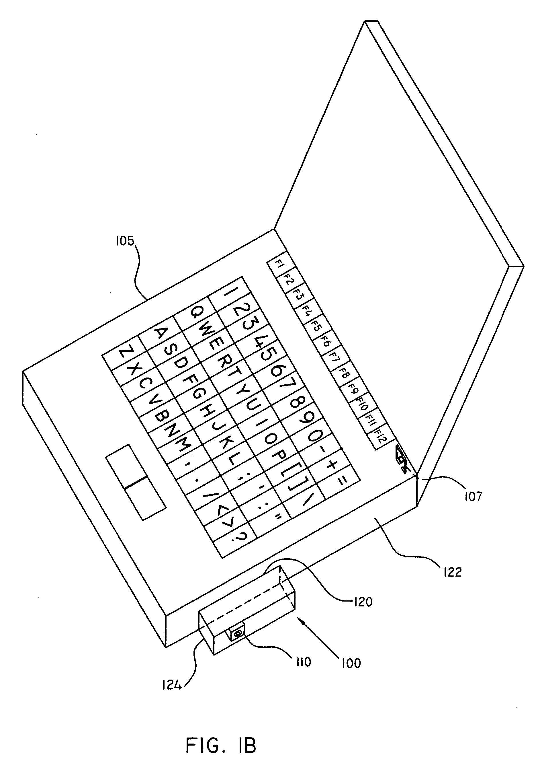
Replacement battery pack with built-in charging circuitry and power connector, and AC adapter for reading charging status of replacement battery pack
a rechargeable battery and circuitry technology, applied in secondary cell manufacturing, electrochemical generators, servicing/maintenance, etc., can solve the problems of power connectors and electronic components that feed power to electronic portable devices while charging a rechargeable battery pack, affecting the power flow in the circuit, and affecting the operation of the circui
- Summary
- Abstract
- Description
- Claims
- Application Information
AI Technical Summary
Benefits of technology
Problems solved by technology
Method used
Image

Examples
Embodiment Construction
[0045] While this invention is susceptible of embodiments in many different forms, this specification and the accompanying drawings disclose only examples of the use of the invention. The invention is not intended to be limited to the embodiments so described, and the scope of the invention will be pointed out in the appended claims.
[0046] The preferred embodiments of the rechargeable replacement batteries and the customized AC adapter according to the present invention are described below with a specific application to a portable computer, such as laptop, notebook and palmtop computers. However, it will be appreciated by those of ordinary skill in the art that the present invention is also well adapted for other portable electronic devices having a battery pack receiving bay for housing a battery pack, such as cellular phones, audio / video devices, power tools, electric shavers and the like.
[0047] Certain terminology is used in the following description for convenience only and is...
PUM
 Abstract
Description
Claims
Application Information