RFID-tag communication device

a radiofrequency identification and communication device technology, applied in the direction of instruments, near-field systems using receivers, burglar alarm mechanical actuation, etc., can solve the problems of difficult control of the phase shifter, the risk of insufficiency of the signal-to-noise ratio of the known rfid-tag communication device, and the cost of a comparatively expensive large phase shifter. , to achieve the effect of simplifying the control of the first cancel signal, simplifying th

Active Publication Date: 2006-11-30
BROTHER KOGYO KK
View PDF11 Cites 40 Cited by
  • Summary
  • Abstract
  • Description
  • Claims
  • Application Information

AI Technical Summary

Benefits of technology

[0051] The first-cancel-signal attenuator may be arranged to change its amount of attenuation of the first cancel signal, to a selected one of different values, so that the first-cancel-signal attenuator can be simplified in construction, and the control to attenuate the first cancel signal can be simplified. The second-cancel-signal attenuator may be similarly arranged.
[0052] Further, the different values to which the amount of attenuation of the first second cancel signal by the first-cancel-signal attenuator is variable are multiples of ½, so that the circuit arrangement of the first-cancel-signal attenuator can be made considerably simple. Further, the control to attenuate the first cancel signal can be simplified by a bit-shift logic using binary digits, for example. This arrangement is applicable to the second-cancel-signal attenuator.
[0053] The first-cancel-signal attenuator may includes a plurality of voltage dividers in the form of a plurality of registers, and a plurality of switches operable to selectively operate the plurality of voltage dividers. In this case, the first-cancel-signal attenuator is simple in construction and economical to manufacture. The second-cancel-signal attenuator may include similar voltage dividers and similar switches.
[0054] The first-cancel-signal attenuator may further include a buffer amplifier functioning as a buffer device, which assures a stable operation of the attenuator. The second-cancel-signal attenuator may further include a similar buffer amplifier.
[0055] The first-cancel-signal D / A converting portion may use four sampling values per one period of an output periodic function. In this case, the noise floor can be held low, permitting a high-speed converting operation of the first-cancel-signal D / A converting portion, and assuring a high signal-to-noise ratio of the analog first cancel signal which has been attenuated by the first-cancel-signal attenuator. Similarly, the second-cancel-signal D / A converting portion may use four sampling values per one period of the output periodic function.

Problems solved by technology

Thus, the known RFID-tag communication device suffers from a risk of insufficiency of the signal-to-noise ratio.
However, the conventional technique to suppress the leakage signal due to the transmission signal transmitted from the RFID-tag communication device and returned to the communication device uses primarily analog processing to control the amplitude and phase of a compensating signal (canceling signal) to suppress the leakage signal, and therefore requires a comparatively expensive large phase shifter.
The conventional technique has a further problem of difficulty of control of the phase shifter.
Thus, there has not been a simple RFID-tag communication device developed for suppression of the leakage signal.

Method used


Image

  • RFID-tag communication device
  • RFID-tag communication device
  • RFID-tag communication device

Examples


embodiment 1

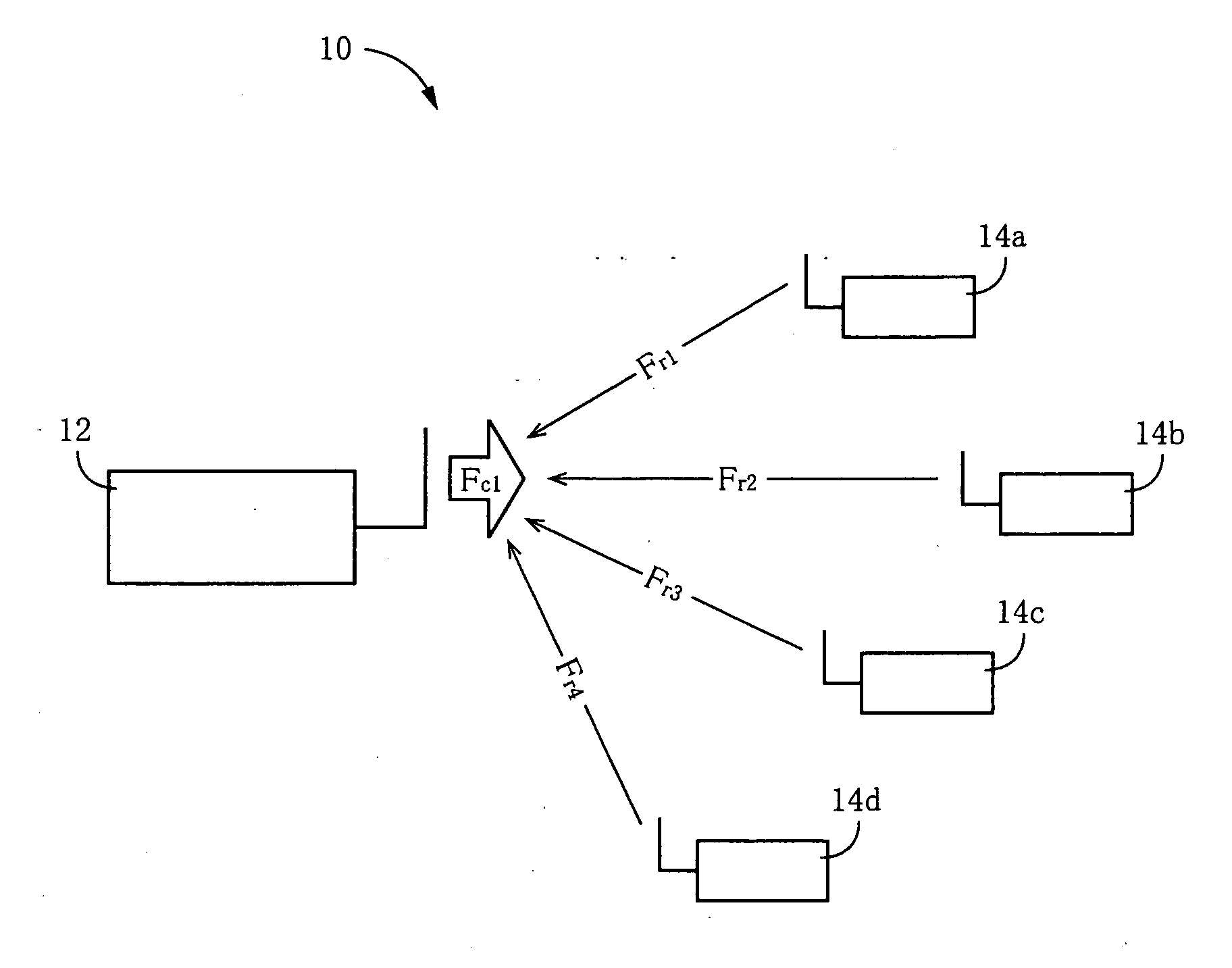
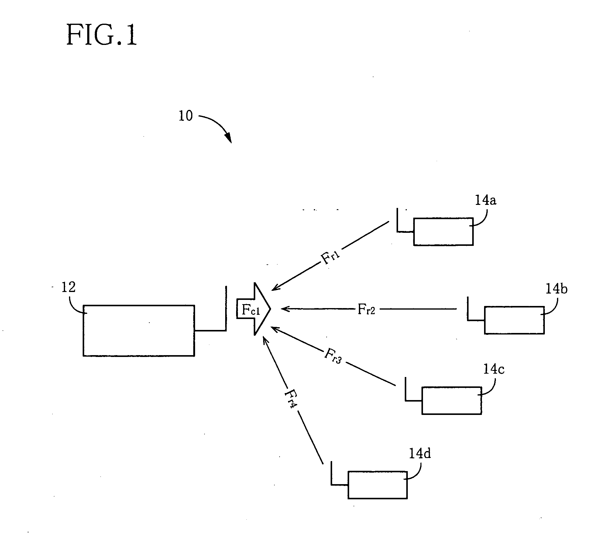
[0110] Reference is first made to FIG. 1 showing an RFID-tag communication system 10 to which the present invention is applicable and which includes an RFID-tag communication device 12 constructed according to a first embodiment of this invention, and a plurality of radio-frequency identification tags (hereinafter abbreviated as “RFID tags”) 14, more specifically, four RFID tags 14a, 14b, 14c and 14d. In the present RFID-tag communication system 10, the RFID-tag communication device 12 serves as an interrogator, while the RFID tags 14 serve as transponders. Namely, the RFID-tag communication device 12 is arranged to transmit a transmission signal in the form of a carrier wave Fc1, while the RFID tags 14a, 14b, 14c, 14d are arranged to receive the carrier wave Fc1, modulate the received carrier wave Fc1 into reply signals in the form of reflected waves Fr1, Fr2, Fr3 and Fr4 (hereinafter collectively referred to as “reflected waves Frf) on the basis of suitable information, and transm...

embodiment 2

[0152] Referring to FIG. 22 showing an electrical arrangement of an RFID-tag communication device 92 constructed according to the second embodiment of this invention, the transmitter / receiver circuit 18 of this RFID-tag communication device 92 includes an RSSI (received signal strength indicator) 94 and an amplitude-signal A / D converting portion 96. The RSSI 94 is arranged to detect the amplitude AR of the received signal received from the transmission / reception separator 50, and the amplitude-signal A / D converting portion 96 is arranged to convert an output of the RSSI 94 indicative of the amplitude AR of the received signal, into a digital signal to be applied to the first-cancel-signal control portion 26. In the present second embodiment, the amplitude AR of the received signal received through the antenna 52 is directly detected by the RSSI 94, and the signal indicative of the detected amplitude AR is converted by the amplitude-signal A / D converting portion 96 into the digital s...

embodiment 3

[0153] Referring to FIG. 23 showing an electrical arrangement of an RFID-tag communication device 98 constructed according to the third embodiment of this invention, the present communication device 98 does not include the function table 40, and includes a digital-transmission-signal output portion 100, a first-cancel-signal output portion 102, and a second-cancel-signal output portion 104 in place of the digital-transmission-signal output portion 20, first-cancel-signal output portion 24 and second-cancel-signal output portion 26. The output portions 100, 102, 104 are operable independently of each other, to generate digital signals in the form of sine-wave or cosine-wave signals, without using the function table 40 provided in the first embodiment. Reference is made to FIG. 24 showing an arrangement of each of the digital-transmission-signal output portion 100, first-cancel-signal output portion 102 and second-cancel-signal output portion 104. Each of these output portions 100, 10...


PUM


Abstract

An RFID-tag communication device including (a) an antenna from which a transmission signal is transmitted toward an RFID tag and through which a reply signal transmitted from the RFID tag in response to the transmission signal is received, for radio communication with the RFID tag, (b) a first-cancel-signal output portion operable to generate a digital first cancel signal for suppressing a leakagel signal from a received signal which is received through the antenna and which contains the leakage signal as well as the rely signal, the leakage signal being a part of the transmission signal which is transmitted from the antenna and which is returned to and received by the antenna, (c) a first-cancel-signal control portion operable to control an amplitude and/or a phase of the first cancel signal generated by the first-cancel-signal output portion, (d) a first-cancel-signal D/A converting portion operable to convert the first cancel signal generated by the first-cancel-signal output portion, into an analog signal, (e) a first signal combining portion operable to combine together the analog first cancel signal generated by the first-cancel-signal D/A converting portion, and the received signal, to obtain a first composite signal.

Description

[0001] The present application is a Continuation-in-Part of International Application No. PCT / JP2005 / 001620 filed Feb. 3, 2005, which claims the benefits of Japanese Patent Application No. 2004-028013 filed Feb. 4, 2004 and No. 2004-251854 filed Aug. 21, 2004.BACKGROUND OF THE INVENTION [0002] 1. Field of the Invention [0003] The present invention relates to an improvement of a radio-frequency identification tag (RFID-tag) communication device capable of radio communication with radio-frequency identification (RFID) tags for writing and reading information on and from the RFID tags. [0004] 2. Description of the Related Art [0005] There is known an RFID system (radio-frequency identification system) wherein an RFID-tag (radio-frequency identification tag) communication device (e.g., an interrogator) reads out information, in a non-contact fashion, from small RFID tags (radio-frequency identification tags, e.g., transponders) on which information is written. In this RFID system, the R...

Claims


Application Information

Patent Timeline
Patent Type & Authority Applications(United States)
IPC IPC(8): H04Q5/22G06K7/00G06K17/00G06K19/07H04B1/59H04B5/02
CPCG06K7/0008G06K19/0723G06K7/10039
Inventor TAKI, KAZUNARIKIYOHARA, YUJINAGAI, TAKUYA
Owner BROTHER KOGYO KK
Why Eureka
Try Eureka