A Machine Producible Directive Closed-Loop Impulse Antenna

a closed-loop impulse and machine-produced technology, applied in the direction of antennas, elongated active element feeds, antenna feed intermediates, etc., can solve the problems of reducing radiation efficiency, unable to fully and simultaneously address the problem, and unable to fully and simultaneously solve the problem. , to achieve the effect of reducing the generation of parasitic side-lobes, reducing the generation of antenna ringing and parasitic side-lobes, and reducing radiation efficiency

Inactive Publication Date: 2006-11-30
REALTRONICS CORP
View PDF16 Cites 8 Cited by
  • Summary
  • Abstract
  • Description
  • Claims
  • Application Information

AI Technical Summary

Benefits of technology

[0020] This invention discloses a novel design that effectively uses conductive antenna elements and one or more matched coax cables behind the reflector back-shield to extract the performance of a slot antenna from an ultra-wideband antenna. The disclosed design also places any form of resistive loading on the outside of the back reflector shield to simultaneously mitigate antenna ringing and parasitic side-lobe generation without sacrificing radiation efficiency. The complete assembly emulates a shielded loop antenna that is typically used for continuous wave emissions; however the device is comprised of geometries that support high performance ultra-wideband dipole transmission.

Problems solved by technology

A primary challenge of antenna design is to mitigate the forgoing problems without distorting the rising edge of the transmitted pulse or destabilizing the ultra wideband impedance characteristics of the antenna.
Lump loading alone does not mitigate the problem of end-fire ringing during the first several cycles and consequently target detection applications are impeded at close range.
However, this payoff is afforded at the expense of a substantial drop in radiation efficiency and an accompanying requirement for more powerful transmitter hardware.
Moreover, the discrete interface at each tapered band creates parasitic side-lobes and induces reflections near the feed point that distorts the rising edge of the transmitted pulse.
This is a particularly prominent problem for target identification systems because the rising edge of the pulse is used to induce reflections that carry sufficient spectral bandwidth to characterize the target.
Each of these prior disclosures employed unique methods to mitigate known problems of the expired patents that were described earlier, yet none fully and simultaneously address the problems of end-fire ringing, consistent impedance characteristics, the rising edge distortion on the transmitted pulse, parasitic side lobe generation, non-uniform polarization artifacts, radiation efficiency, or any combination thereof.
While prior art does substantially improve select antenna parameters, these methods introduce new design tradeoffs that interfere with antenna performance.

Method used


Image

  • A Machine Producible Directive Closed-Loop Impulse Antenna
  • A Machine Producible Directive Closed-Loop Impulse Antenna
  • A Machine Producible Directive Closed-Loop Impulse Antenna

Examples


Embodiment Construction

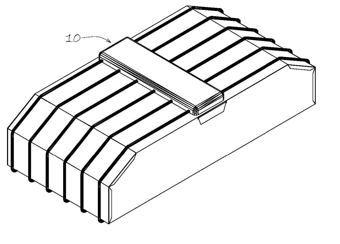
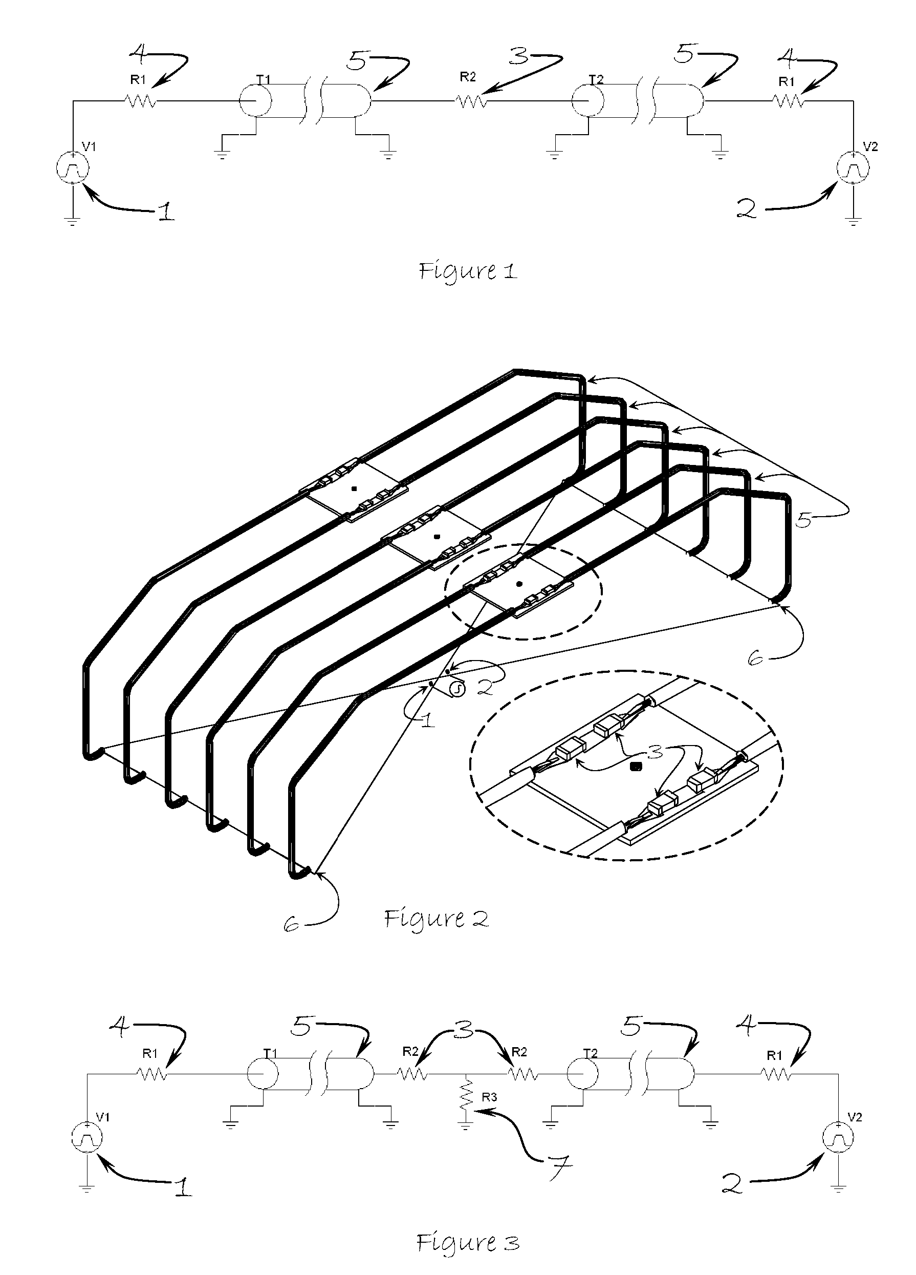
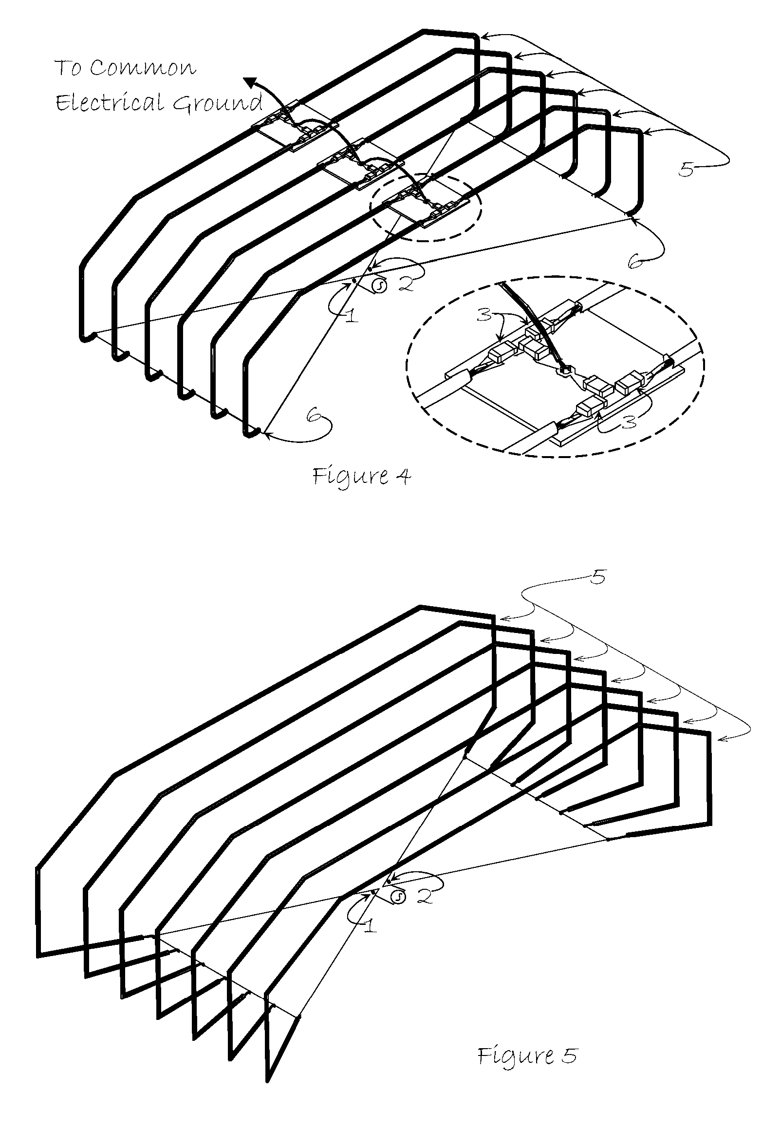
[0030] Broadband antennae are commonly energized by two matched signal generators to simultaneously couple oppositely polarized impulse signals onto the feed-points of an antenna as illustrated at 1 and 2 in FIGS. 1 through 5. Impedance mismatches at these feed point interfaces, which are typically small, and at the flare-end interfaces that are illustrated at 6 in FIGS. 2, 4, 5 and 6, which are typically large, induce reflections that rapidly deteriorate antenna performance. This is a particularly prominent problem with broadband antennas because it is difficult to design impedance interfaces that are consistent over a wide spectrum.

[0031] The disclosed invention uses broadband shielded cables to smoothly guide the transmitted energy away from the antenna flare end. The matched coax cables direct this energy to an assembly of impedance loads like those shown at 3 in FIGS. 1 thru 4 that facilitate energy cancellation between the oppositely polarized impulses. In an alternative embo...


PUM


Abstract

A low-cost high performance ultra wideband antenna that combines coax-shielded cables with properly selected and carefully positioned load balancing components to form a novel closed loop dipole is disclosed. The apparatus includes a closed-loop broadband antenna circuit that may be comprised of single or multiple conductive radiating elements that are electrically connected to one another at the flare-end of each antenna leaf by at least one shielded conductor in one or more shielded cables of any type. The shielded cable portion of the closed loop circuit is interrupted by load impedance tapered regions that are positioned in an area that does not interfere or interferes minimally with antenna performance. The closed-loop broadband antenna circuit and the feed-point connections may be grounded by a separate path within the device. The disclosed approach simultaneously mitigates known problems of parasitic side lobes, antenna ringing, and RF coupling that commonly plague prior art.

Description

CROSS-REFERENCE TO RELATED APPLICATIONS [0001] Current US Class: 343 / 793, 343 / 807, 343 / 845 [0002] International Class: H01Q 001 / 38, 48 [0003] Field of Search: 250 / 216, 342 / 379, 343 / 727, 730, 739, 740, 775, 777, 793, 795, 807, 813, 814, 815, 819, 820, 826, 828, 841, 845, 912, 913 OTHER PUBLICATIONS [0004] [1] R. L. Carrel, “The characteristic impedance of two infinite cones of arbitrary cross section,” IEEE Trans. Antennas Propagation, vol. AP-6, no. 2, pp. 197-201, 1958. [0005] [2] T. T. Wu and R. W. P. King, “The Cylindrical Antenna with Nonreflecting Resistive Loading”, IEEE Transactions on Antennas and Propagation, vol. AP-13, No. 3, pp. 369-373, May 1965. [0006] [3] Shen, “An Experimental Study of the Antenna with Nonreflecting Resistive Loading”, IEEE Transactions on Antennas and Propagation, vol. API 5, No. 5, Sep. 1967, pp. 606-611. [0007] [4] Clapp, “A Resistively Loaded, Printed Circuit, Electrically Short Dipole Element for Wideband Array Applications”, IEEE, May 1993, pp....

Claims


Application Information

Patent Timeline
Patent Type & Authority Applications(United States)
IPC IPC(8): H01Q9/16
CPCH01Q9/26H01Q9/28H01Q9/265
Inventor ASKILDSEN, BERNT ASKILDTHOMPSON, SCOTT RANDALL
Owner REALTRONICS CORP
Why Eureka
Try Eureka