
Method for providing human input to a computer

a technology of human input and computer, which is applied in the direction of static indicating devices, instruments, electric devices, etc., can solve the problems of limiting the resolution or the size or both of the display to which entry is made, and no known commercial devices can solve the problem of limiting the resolution or the size of the display, so as to achieve cost-effectiveness, unique dynamic detection ability, and cost-competitive

Inactive Publication Date: 2006-11-30
TACTILE FEEDBACK TECH
View PDF43 Cites 21 Cited by
  • Summary
  • Abstract
  • Description
  • Claims
  • Application Information

AI Technical Summary

Benefits of technology

"The invention is a touch screen technology that can be used in various applications such as aids for the disabled, data entry over larger surfaces, and virtual reality and simulation. It can provide a 3D touch screen capability and can be easily incorporated into home projection TVs and video arcade games. The technology is also adaptable to different touch screen devices such as glass, plastic, armor plate, and steel. Overall, the invention improves the interaction between humans and computers and enhances the experience of simulating and interacting with virtual environments."

Problems solved by technology

No known commercial devices can do this, and a limited technology set exists for this purpose—especially over large extensive screen or pad areas.
In addition, conventional technologies typically limit the resolution or the size or both of the display to which entry could be made.
For example, touch screen data entry is commonly available over a standard let us say 12″ to 19″ computer terminal to the level of 1 part in 40 in both X and Y. While this suffices for many computer data entry purposes (e.g. selecting icons), it is certainly not suitable for high resolution drawing on a screen or other such activities.
Prior art is lacking which can accommodate high resolution “touch” or other inputs easily over large surfaces such as for example data displays in military war rooms and the like.
In addition, high resolution seems possible in prior art digitizers only by moving special apparatus or using special writing instruments such as a conductive pen, and high resolution touch screens are difficult with digital technologies such as the discrete grids.
Such grids also run the risk of degrading the light transmission characteristics of the screen.
Another drawback of most conventional data entry systems today is that they can only respond to one point at a time.
Accuracy is also a problem with most digitizers and touch screens, in particular those using analog principles (e.g. the Bowman reference above).
There is virtually no evidence of 3-D capability in the finger touch devices.

Method used


Image

  • Method for providing human input to a computer
  • Method for providing human input to a computer
  • Method for providing human input to a computer

Examples


Embodiment Construction

[0083]FIG. 1

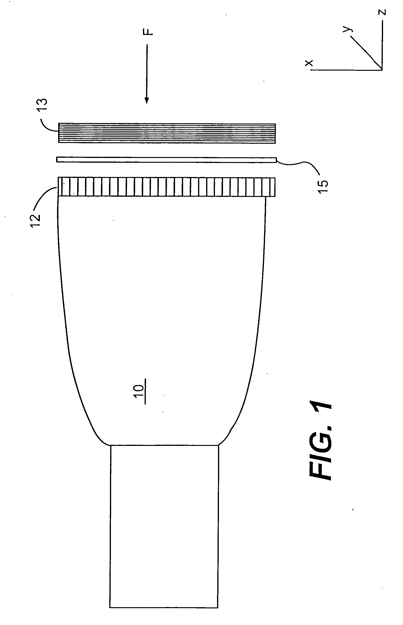
[0084] A typical prior art touch screen arrangement which, like the invention, operates in a physical touching mode, is shown in FIG. 1. In this arrangement, a transparent member 12 comprised of a periodic set of conductive bars is placed on the front of CRT tube 10. It is opposed by a second member 13, whose surface includes a set of conducting bars in the orthogonal direction. The two conducting surfaces are separated by a third transparent insulating medium 15, having on array of holes in it which can allow the force of touching to push the front surface through to the rear surface thereby making contact. By scanning the conductors electronically, at the point of contact, a signal is generated which then gives the XY location on the screen of the touch.

[0085] The resolution of the conventional touch screen technology represented by FIG. 1 is limited in that the horizontal / vertical lines must be wide enough spaced so that one can push through without touching adjacent...


PUM


Abstract

A method and apparatus are provided for controlling at least one function of a motor vehicle utilizing a member such as a touch pad or touch screen for receiving inputs of the driver thereof, which member is generally located on the dashboard of the vehicle and may be plastic and curvilinear and may contain actuation devices such as knobs, sliders and switches. A computer analyzes data inputted by the driver and an active tactile feedback signal may be provided to the touch member to signal the driver.

Description

CROSS REFERENCE TO RELATED APPLICATIONS [0001] This application is a continuation of application Ser. No. 09 / 435,854 filed Nov. 8, 1999, now a Patent; which is continuation of application Ser. No. 08 / 496,908 filed Jun. 29, 1995, now U.S. Pat. No. 5,982,352; which is a continuation-in-part of application Ser. No. 08 / 290,516 filed Aug. 15, 1994, now U.S. Pat. No. 6,008,800; which is a continuation of application Ser. No. 07 / 946,588 filed Sep. 18, 1992, now abandoned. All of these prior applications are hereby incorportated by reference. [0002] The disclosures of the following U.S. patents and co-pending patent applications are also incorporated herein by reference: [0003] U.S. Pat. No. 4,629,319 (“D-SIGHT”) [0004] U.S. Pat. No. 4,394,683 (“Circuits”) [0005] U.S. Pat. No. 4,373,804 (“Turbine”) [0006] U.S. Ser. No. 08 / 290,516 filed Aug. 15, 1994 (“Man Machine Interface”) [0007] U.S. Ser. No. 08 / 203,603, filed Feb. 28, 1994 (“Robot Vision Using Target Holes . . . ”) [0008] U.S. Ser. No. ...

Claims


Application Information

Patent Timeline
Patent Type & Authority Applications(United States)
IPC IPC(8): G09G5/00
CPCG06F3/011G06F3/016G06F2203/04109G06F3/0425G06F3/0304
Inventor PRYOR, TIMOTHY R.
Owner TACTILE FEEDBACK TECH
Learn More