Gas turbine moving blade having a platform, a method of forming the moving blade, a sealing plate, and a gas turbine having these elements

a technology of moving blades and gas turbines, applied in the direction of blade accessories, engines/engines, blade accessories, etc., can solve the problems of easy cracking and great thermal stress

Inactive Publication Date: 2006-11-30
MITSUBISHI HEAVY IND LTD
View PDF6 Cites 61 Cited by
  • Summary
  • Abstract
  • Description
  • Claims
  • Application Information

AI Technical Summary

Benefits of technology

[0008] As described above, in the moving blades of a gas turbine, cooling air is supplied to cool each of the blades and a platform and thus to suppress increases in the temperatures of the respective metals due to a high-temperature combustion gas. In the moving blades of the gas turbine, a significant difference in mass exists between the platform and a profile section of each blade, and if a significant temperature difference occurs between both, this will cause a great thermal stress. The occurrence of a great thermal stress between the platform and the profile section of the blade makes cracking prone to occur particularly at sections exposed to the most thermally-severe conditions. These sections include, for example, the blade and a hub located at the trailing edge where the platform is planted. The present invention focuses particularly on the thermal stress of the platform and on the burned portions. Such damage is caused by a combination of creep rupture based on many years of high-temperature, high-stress operation, and fatigue-based destruction due to the stresses repeatedly applied with each start / stop operation. To prevent the damage, therefore, it is necessary to reduce to the lowest possible level the temperatures of and (thermal) stresses on sections prone to have concentrated stresses (i.e., the platform base sections at leading and trailing edges of the blade).
[0025] In the above gas turbine structure, the entire gas turbine can effectively use cooling air.

Problems solved by technology

In the moving blades of the gas turbine, a significant difference in mass exists between the platform and a profile section of each blade, and if a significant temperature difference occurs between both, this will cause a great thermal stress.
The occurrence of a great thermal stress between the platform and the profile section of the blade makes cracking prone to occur particularly at sections exposed to the most thermally-severe conditions.
Such damage is caused by a combination of creep rupture based on many years of high-temperature, high-stress operation, and fatigue-based destruction due to the stresses repeatedly applied with each start / stop operation.

Method used


Image

  • Gas turbine moving blade having a platform, a method of forming the moving blade, a sealing plate, and a gas turbine having these elements
  • Gas turbine moving blade having a platform, a method of forming the moving blade, a sealing plate, and a gas turbine having these elements
  • Gas turbine moving blade having a platform, a method of forming the moving blade, a sealing plate, and a gas turbine having these elements

Examples


embodiment 1

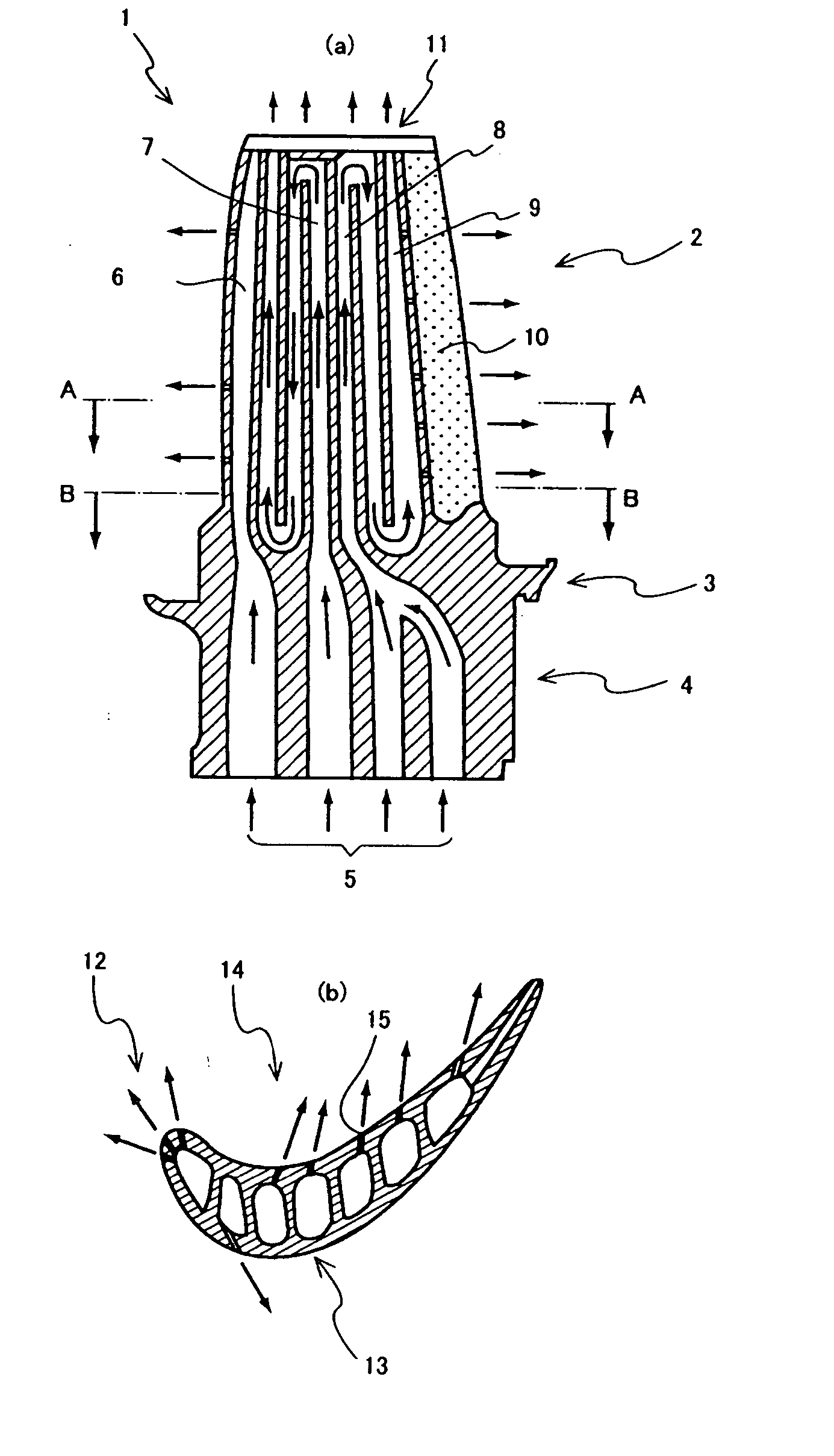
[0038]FIG. 1(a) shows a longitudinal section of, for example, a first-stage gas turbine moving blade according to Embodiment 1 of the present invention, and FIG. 1(b) is a cross-sectional view of section A-A in FIG. 1(a).

[0039] A gas turbine moving blade 1 includes a blade 2 that forms a profile, a platform 3 bonded with a rooted section of the blade 2, and a shank 4 located under the platform 3. The interior of the blade 2 is constructed so that cooling air is first supplied from a blade root (Christmas-tree-like shape not shown here) that leads to a rotor (not shown) disposed under the blade, to cooling air passages 5. The cooling air is then supplied to a leading-edge passage 6 and serpentine fluid passages 7,8, each disposed inside the blade, so as to cool the blade interior. In a cooling passage 9, part of the cooling air is blown out from a trailing edge 10 to cool the edge 10, and the remainder of the cooling air is blown out from a blade top 11 into a gas path. In addition,...

embodiment 2

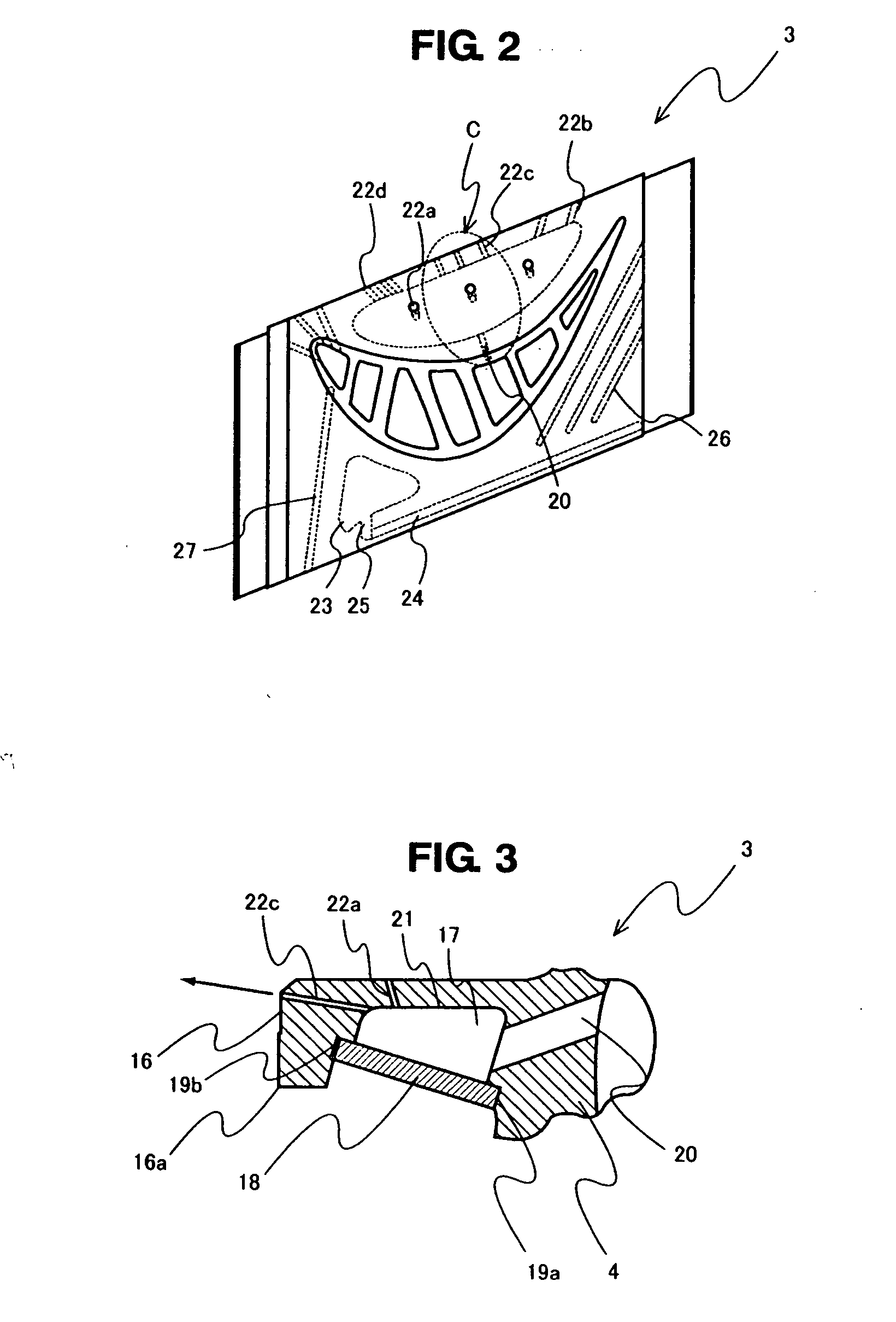
[0046]FIG. 6 shows a form of installation of a sealing plate according to another embodiment, with a curved sealing plate 18 installed between a platform peripheral-edge lower end 16a and a shank groove 19a demonstrated. This installation form is suitable when a large cavity is to be formed, and when the lower end of the platform cannot be easily grooved.

embodiment 3

[0047] FIGS. 7(a) to 7(g) show plane and lateral-face shapes of various types of sealing plates. FIG. 7(a) shows a flat type composed of one flat plate, and FIG. 7(b) shows an arch type of plate having a thin and long dimple 18-1 extending along almost the entire length of the plate. FIG. 7(c) shows a sealing plate provided with a container-type dimple 18-2 forming a flat recess in the center. Furthermore, FIG. 7(d) shows a recessed type of sealing plate having two independent, thin and long dimples 18-3 and 18-4 approximately in the center. Besides, FIG. 7(e) shows a recessed combination type of sealing plate having a thin and long dimple 18-5 or 18-6 on both the surface and reverse side of the plate. FIG. 7(f) shows a sealing plate having a plurality of independent, protruding spherical dimples on the surface or reverse side of the plate. FIG. 7(g) shows, as a modified type of plate in FIG. 7(a), a connected type of sealing plate constituted by several plates 18-8 and 18-9 bonded ...


PUM


Abstract

A platform of a gas turbine moving blade suppresses the effects of thermal elongation and thus improves cooling performance. A structure is constituted by a peripheral edge of a platform of a gas turbine moving blade, a bottom of the platform, and a shank of the moving blade. A cavity is blocked by disposing a sealing plate so as to seal the recessed section, while a supply route is formed for supplying air from cooling passages through an interior of the shank to the cavity, each of the passages being for air-cooling the interior of the gas turbine moving blade with air blown out from the cavity to a surface of the platform. A method of appropriately installing the sealing plate is also disclosed.

Description

BACKGROUND OF THE INVENTION [0001] 1. Field of the Invention [0002] The present invention relates to a gas turbine moving blade having a platform and is intended to suppress any effects of thermal elongation on the platform and thus to improve cooling performance thereof [0003] 2. Description of the Prior Art [0004]FIG. 9 is a perspective view of a typical platform 103 of a gas turbine moving blade 101 used primarily as a first-stage moving blade. Structurally, the moving blade has a platform integrated with a profile and profile-equipped root forming a blade 102. Below the platform, a blade root 151 of a Christmas-tree shape is formed and, as shown in FIG. 10, engaged to a groove 162 formed into the same shape as that of a rotor disc 161. Such plural moving blades are fixed in a parallel fashion to the grooves provided in the rotor disc, and there is a cavity 117 formed by a platform of the same stage and a shank 104 of the moving blade. The cavity is provided to supply sealing air...

Claims


Application Information

Patent Timeline
Patent Type & Authority Applications(United States)
IPC IPC(8): F01D5/18
CPCF01D5/187F05D2240/55F05D2240/81F05D2260/2214F05D2260/2212
Inventor TORII, SHUNSUKESOECHTING, FRIEDRICHYURI, MASANORI
Owner MITSUBISHI HEAVY IND LTD
Why Eureka
Try Eureka