Total heat exchanger and ventilation system using the same

a technology ventilation system, which is applied in the direction of ventilation system, domestic cooling apparatus, heating types, etc., can solve the problems of limited height of total heat exchanger, affecting the efficiency of ventilation system,

Inactive Publication Date: 2006-11-30
LG ELECTRONICS INC
View PDF9 Cites 27 Cited by
  • Summary
  • Abstract
  • Description
  • Claims
  • Application Information

AI Technical Summary

Benefits of technology

[0012] An object of the present invention is to provide a total heat exchanger having an increased total heat efficiency, and a ventilation system using the total heat exchanger.
[0013] Another object of the present invention is to provide a total heat exchanger capable of achieving a reduction in flow resistance, and a ventilation system using the total heat exchanger.

Problems solved by technology

Generally, air present in a confined space, for example, an indoor space, is gradually contaminated as time passes in accordance with repeated respiration of living beings in the indoor space.
However, the total heat exchanger has the following problems.
First, the height of the total heat exchanger, which is installed in the interior of a ceiling, is restricted because the ceiling is designed to have a restricted thickness.
Second, the flow rate of air passing through the heat exchanging element is too high to enable the heat exchanging element to effectively perform a desired heat exchanging operation.
As a result, a degradation in the efficiency of the total heat exchanger occurs.
Third, there is a problem in that an increase in flow resistance occurs because the flow directions of indoor air and outdoor air passing through the heat exchanging element are greatly varied.

Method used


Image

  • Total heat exchanger and ventilation system using the same
  • Total heat exchanger and ventilation system using the same
  • Total heat exchanger and ventilation system using the same

Examples


first embodiment

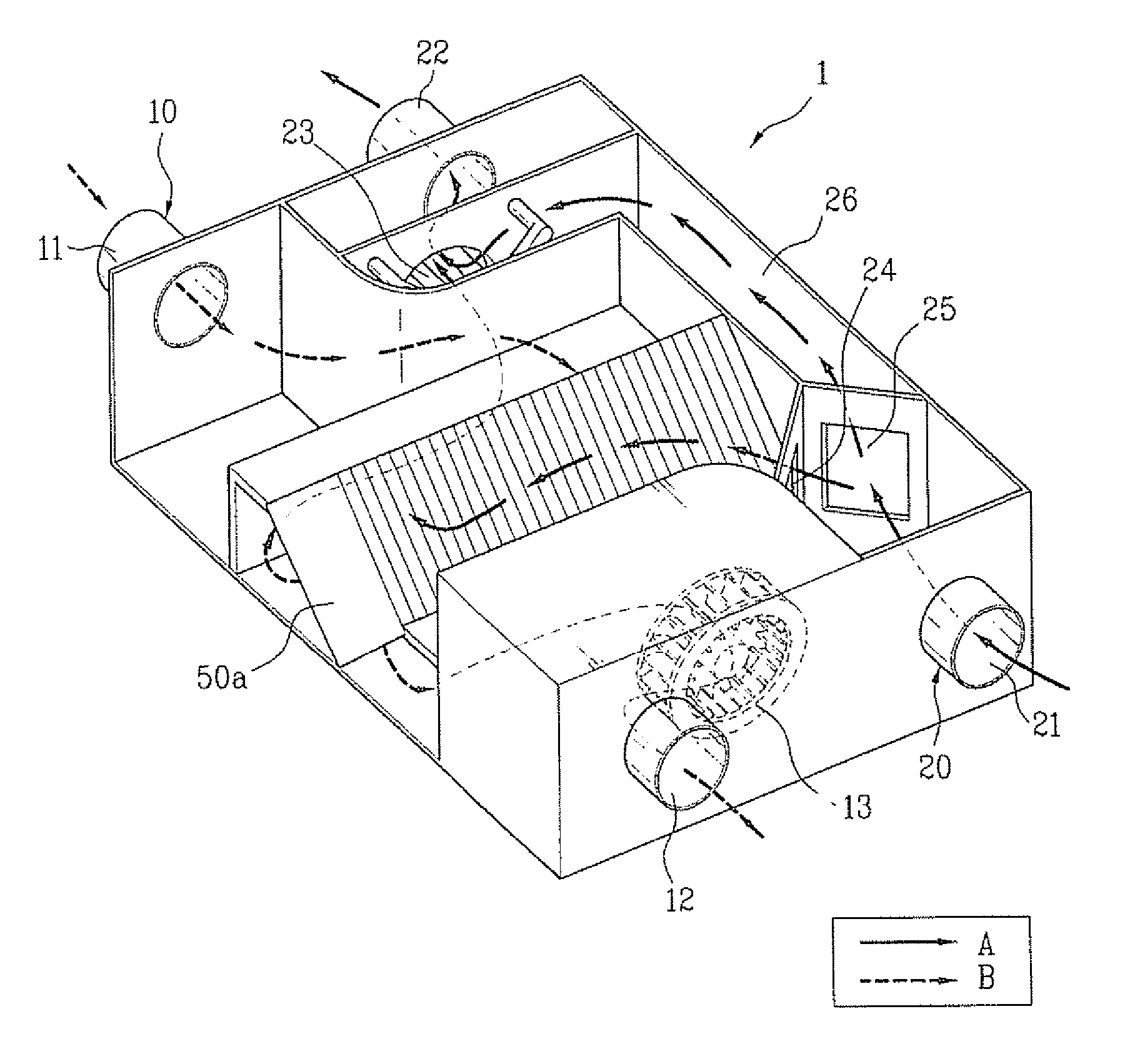
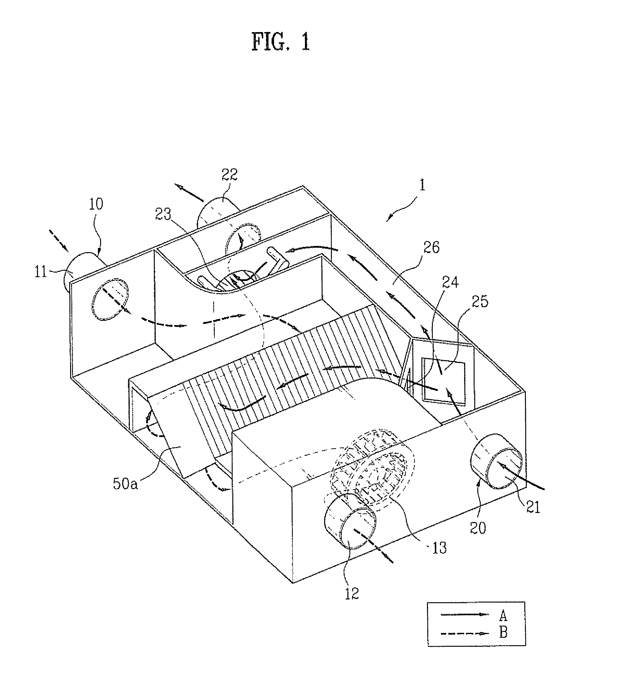
[0045] Hereinafter, the total heat exchanger according to the present invention will be described with reference to FIGS. 1 to 3B.

[0046] The total heat exchanger includes an air supply duct 10 for guiding outdoor air to an indoor space, an air discharge duct 20 for guiding indoor air to the outdoors, and a heat exchanging element 50a for heat-exchanging the indoor air with the outdoor air. The total heat exchanger may further include an air supply fan 13 for sucking the outdoor air, and supplying the sucked air to the indoor space, and an air discharge fan 23 for sucking the indoor air, and discharging the sucked air to the outdoors.

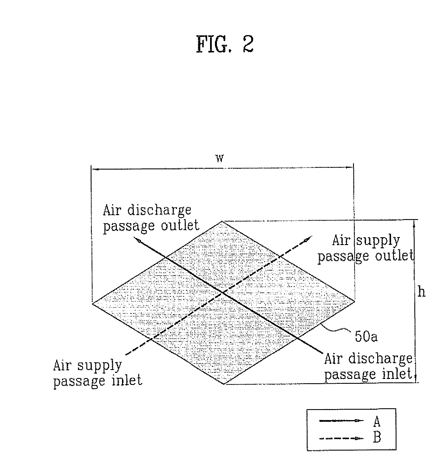
[0047] The heat exchanging element 50a is arranged at a region where an outdoor air flow guided by the air supply duct 10 and an indoor air flow guided by the air discharge duct 20 cross each other. The heat exchanging element 50a heat-exchanges the indoor air with the outdoor air through exchange of sensible heat using a temperature difference between ...

second embodiment

[0073] Hereinafter, the total heat exchanger according to the present invention will be described with reference to FIGS. 4 and 5.

[0074] The basic configuration of the second embodiment of the total heat exchanger according to the present invention is identical to that of the first embodiment as described above. In the second embodiment, however, the total heat exchanger includes a plurality of heat exchanging elements 50b arranged in series in a flow direction of air in the total heat exchanger.

[0075] As described above, there is a restriction in increasing the cross-sectional height of a heat exchanging element due to restrictions in the design of the construction in which the total heat exchanger is installed. When the heat exchanging elements 50b are arranged in series in a flow direction of air in the total heat exchanger, it is possible to achieve an enhancement in heat exchange efficiency without an increase in the cross-sectional height of the heat exchanging elements 50b. ...

third embodiment

[0083] Hereinafter, the total heat exchanger according to the present invention will be described with reference to FIG. 6.

[0084] In accordance with this embodiment, the total heat exchanger includes an air-supply-side fan-motor assembly 130 and an air-discharge-side fan-motor assembly 230.

[0085] The air-supply-side fan-motor assembly 130 includes a plurality of air supply fans 131 each having a rotating shaft extending perpendicularly to the discharge direction of outdoor air. similarly, the air-discharge-side fan-motor assembly 230 includes a plurality of air discharge fans 231 each having a rotating shaft extending perpendicularly to the discharge direction of indoor air.

[0086] The air supply fans 131 are driven by a single dual-axial motor 132. Similarly, the air discharge fans 231 are driven by a single dual-axial motor 232. Since the air supply fans 131 and air discharge fans 231 are driven by the associated dual-axial motors 132 and 232, respectively, it is possible to prod...


PUM


Abstract

A total heat exchanger having a structure capable of achieving an enhancement in total heat efficiency, and a ventilation system using the total heat exchanger are disclosed. The total heat exchanger includes an air supply duct for guiding outdoor air to an indoor space, an air discharge duct for guiding indoor air to the outdoors, an air supply fan arranged at one side of the air supply duct, the air supply fan sucking the outdoor air, and supplying the sucked air to the indoor space, an air discharge fan arranged at one side of the air discharge duct, the air discharge fan sucking the indoor air, and discharging the sucked air to the outdoors, and a heat exchanging element arranged at a region where the indoor air and the outdoor air cross each other, the heat exchanging element heat-exchanging the indoor air with the outdoor air. The heat exchanging element has a shape causing the indoor air and the outdoor air to flow through the heat exchanging element while forming an acute angle with respect to each other.

Description

[0001] This application claims the benefit of Korean Patent Application No. P2005-46326, filed on May 31, 2005, which is hereby incorporated by reference as if fully set forth herein. BACKGROUND OF THE INVENTION [0002] 1. Field of the Invention [0003] The present invention relates to a total heat exchanger and a ventilation system using the same, and more particularly, to a total heat exchanger which has an improved structure so as to have an increased heat exchange area, thereby being capable of achieving an enhancement in total heat efficiency, and a ventilation system using the total heat exchanger. [0004] 2. Discussion of the Related Art [0005] Generally, air present in a confined space, for example, an indoor space, is gradually contaminated as time passes in accordance with repeated respiration of living beings in the indoor space. Accordingly, it is necessary to frequently replace contaminated air in the indoor space with fresh outdoor air. To this end, a ventilation system u...

Claims


Application Information

Patent Timeline
Patent Type & Authority Applications(United States)
IPC IPC(8): F25D17/06F24F7/00
CPCF24F3/147Y02B30/563F24F2012/007F24F12/006Y02B30/56F24F7/08F28F3/00
Inventor KIM, KYUNG HWANCHOI, KEUN HYOUNGCHOI, DONG WHANCHOI, HO SEON
Owner LG ELECTRONICS INC
Why Eureka
Try Eureka