Power transmission device

a technology of transmission device and torque limiter, which is applied in the direction of gearing control, gearing elements, gearing, etc., can solve the problems of affecting the operation accuracy the appearance of the torque limiter not operating, so as to achieve the effect of reducing the loss of transmitted power and high fastening strength of the torque limiter

Inactive Publication Date: 2006-11-30
DENSO CORP +1
View PDF3 Cites 10 Cited by
  • Summary
  • Abstract
  • Description
  • Claims
  • Application Information

AI Technical Summary

Benefits of technology

[0008] The present invention has been accomplished to solve the above problems. An object of the present invention is to provide a power transmission device used for a compressor characterized in that: even when a diameter of a rotary shaft is small, a high fastening strength of a torque limiter can be ensured without deteriorating a mechanical strength of the rotary shaft; and a loss of transmitted power can be decreased.
[0009] A power transmission device of an embodiment of the present invention comprises: a pulley 1 rotated by a drive source; a cap 4 attached to one end portion of a rotary shaft 5; a power shut-off member 3, one face of which is screwed to an outer circumferential screw portion of the cap 4, the other face of which is mechanically connected to the pulley 1, the power shut-off member 3 being broken when an intensity of torque transmitted between the rotary shaft 5 and the pulley 1 is increased to higher than a predetermined intensity of torque and the torque transmission can be shutted off; and a rotary shaft screw portion provided on the rotary shaft 5, screwed to an inner circumferential screw portion provided inside the cap 4, wherein an expanded diameter portion, the diameter of which is larger than that of the screw of the rotary shaft screw portion, is provided in a root portion of the rotary shaft 5 screw portion, a first seat surface opposed to the expanded diameter portion is provided on an inner circumferential face of the cap 4, a second seat surface opposed to a shaft end of the rotary shaft 5 is provided on a bottom face of the cap 4, and an axial force generated by the screw engaging portion of the rotary shaft 5 and the cap 4 is received by at least one of the first and the second seat surface so as to transmit the torque. Due to the above structure, even when a rotary shaft of a small diameter is used, it is possible to endure a high fastening strength with the torque limiter (power shut-off member) without deteriorating the mechanical strength of the rotary shaft 5.
[0010] A power transmission device of another embodiment of the present invention comprises: a pulley 1 rotated by a drive source; a cap 4 engaged with one end portion of a rotary shaft 5 so that the cap 4 can be rotated integrally with the rotary shaft 5; and a power shut-off member 3, one face of which is screwed to an outer circumferential screw portion provided outside the cap 4, the other face of which is mechanically connected to the pulley 1, the power shut-off member 3 being broken by an axial force generated by the outer circumferential screw portion when an intensity of torque transmitted between the rotary shaft 5 and the pulley 1 increased to higher than a predetermined intensity of torque and the torque cannot be transmitted. Due to the above structure, even when a rotary shaft of a small diameter is used, it is possible to endure a high fastening strength with the power shut-off member without deteriorating the mechanical strength of the rotary shaft.
[0011] A power transmission device of still another embodiment of the present invention comprises; a pulley 1; a hub 2; a power shut-off member 3; and a cap 4, one inner face of which has an inner circumferential screw, which is screwed to a screw portion of the rotary shaft 5, and the other outer face of which has an outer circumferential screw portion, which is screwed to the power shut-off member 3, wherein power is transmitted by the cap 4 from the power shut-off member 3 to the rotary shaft 5. In addition to this screw fastening portion, by utilizing a seat surface B or by utilizing both a seat surfaces A and B which are the seat surface A of the end face 5a of the forward end portion provided on the rotary shaft 5 and the seat surface B of the screw root portion 5d, torque can be transmitted between the rotary shaft 5 and the cap 4. Due to the above structure it is possible to prevent a reduction in the mechanical strength of the rotary shaft 5, and further, it is possible to reduce the diameter of the rotary shaft 5. Therefore, it is possible to reduce a sliding loss caused in the shaft sealing device of the rotary shaft 5 and the bearing device.

Problems solved by technology

The portion of the power transmitting route is broken by utilizing an excessively strong axial force generated in the screw fastening portion by an excessively high intensity of torque generated in the case where the compressor has seized, so that the power transmission route can be cut off.
Therefore, the operational accuracy of the torque limiter is affected by an intensity of torque generated at the time of seizure and by a coefficient of friction between the screw portion and the seat surface which compose an engaging and fastening portion.
When the diameter of the rotary shaft is reduced in a conventional power transmission having the above torque limiter, another problem may be caused.
That is, when the diameter of the rotary shaft is reduced in the fastening structure of fastening the hub and the rotary shaft of the compressor in the conventional power transmission device for transmitting power to the compressor, a problem that the torque limiter does not operate appears.

Method used


Image

  • Power transmission device
  • Power transmission device
  • Power transmission device

Examples


Embodiment Construction

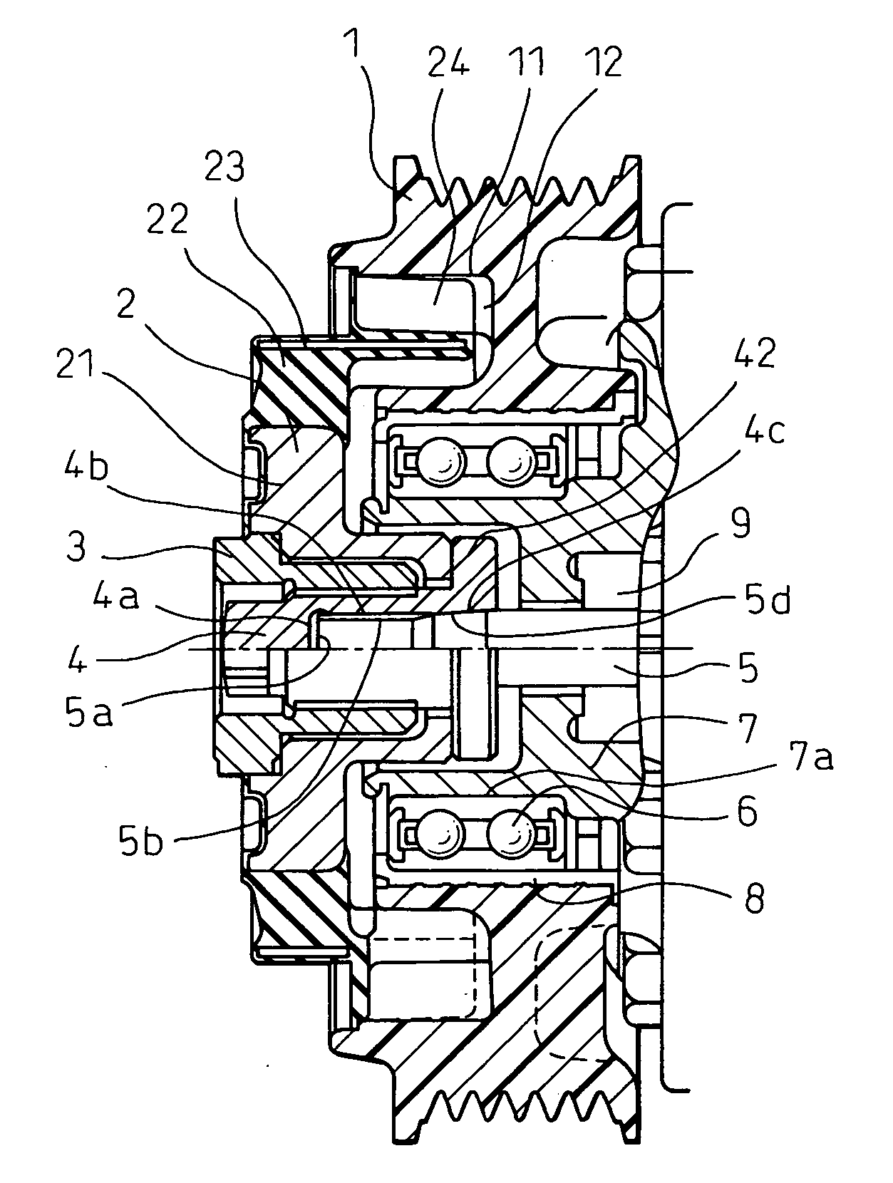
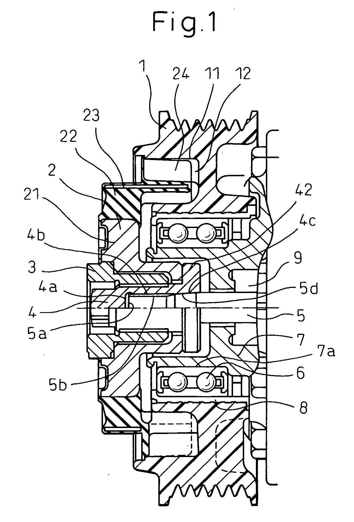
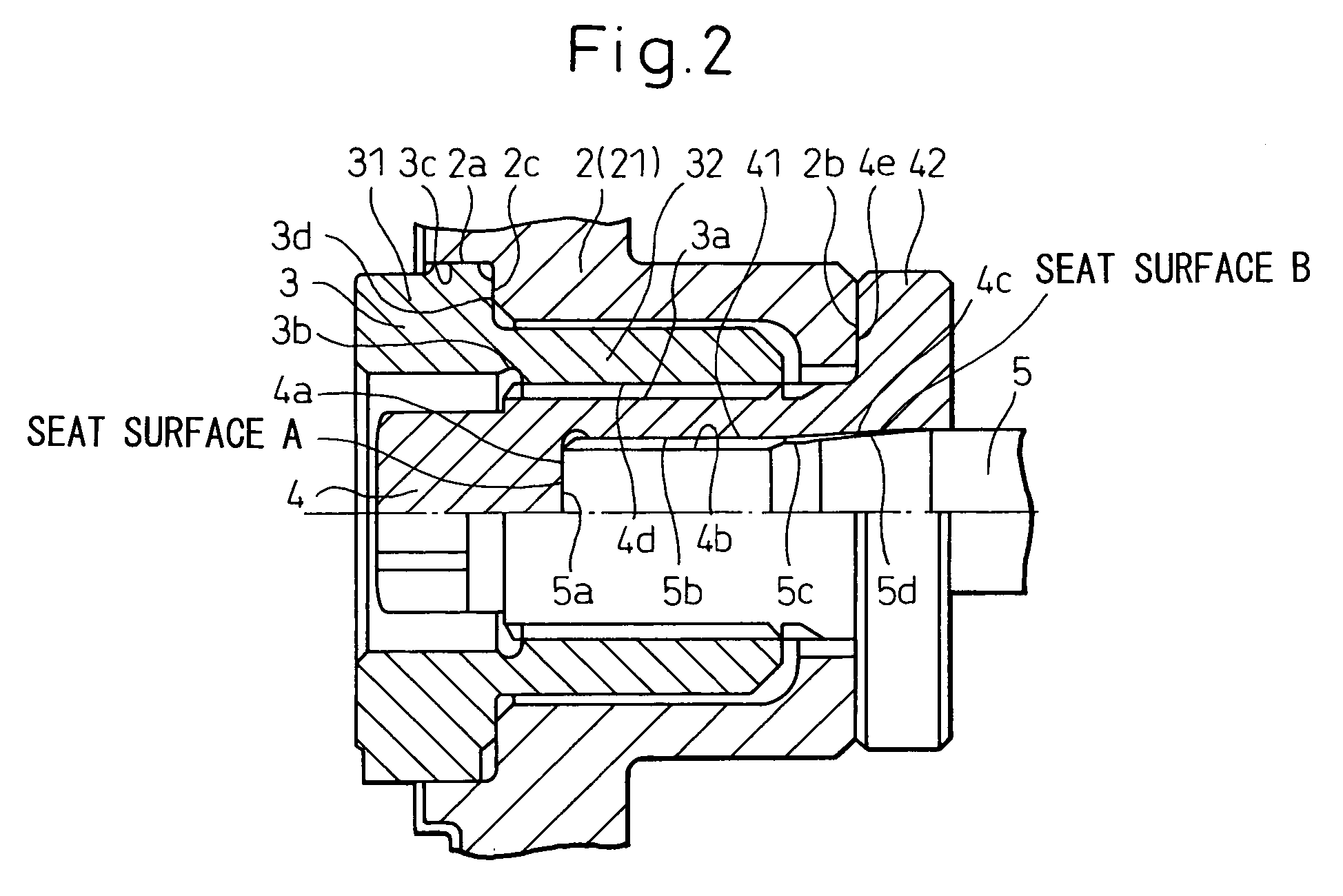
[0023] Referring to the drawings, a power transmission device of an embodiment of the present invention will be explained below. The power transmission device of the present invention is preferably incorporated into a compressor of an air conditioner for vehicle use (a car air conditioner). FIG. 1 is a sectional view showing an overall structure of the power transmission device of the embodiment of the present invention, and FIG. 2 is an enlarged sectional view showing a primary portion of the power transmission device shown in FIG. 1. The power transmission device of the present invention transmits power (torque) between a pulley 1, which is rotatablely attached to a casing 7 of a compressor which is a driven side rotary machine obtaining power from an engine or motor, and a hub 2 fixed to a rotary shaft 5 of the compressor, which is a driven side rotary machine, via a cap 4 and a power shut-off member 3 which functions as a torque limiter. The pulley 1 and the hub 2 are arranged o...


PUM


Abstract

A power transmission device includes a pulley 1, a hub 2 and a power shut-off member 3 and further includes a cap 4, one face of which is fastened to an end portion of a rotary shaft 5 by screwing and the other face of which is fastened to the power shut-off member by screwing, so as to transmit power from the power shut-off member to the rotary shaft 5. Power is transmitted between the rotary shaft and the cap not only by this screw fastening portion but also by utilizing a seat surface B or both seat surfaces A and B, wherein the seat surface A is formed on a forward end face 5a provided on the rotary shaft and the seat surface B is formed on a screw root portion (an expanded diameter portion) 5d.

Description

BACKGROUND OF THE INVENTION [0001] 1. Technical Field of the Invention [0002] The present invention relates to a power transmission device having a torque limiter function. More specifically, the present invention relates to a power transmission device preferably used in a compressor used for a car air conditioner driven by a power source, such as an engine, via a belt. [0003] 2. Description of the Related Art [0004] A refrigerant compressor used for a car air conditioner is driven by a power source, such as an engine, via a belt, a pulley and so forth, In order to disconnect the refrigerant compressor from the engine when necessary, an electromagnetic clutch is interposed between the refrigerant compressor and the engine. However, if no electromagnetic clutch is interposed between the refrigerant compressor and the engine, the manufacturing cost can be reduced. Therefore, the electromagnetic clutch is omitted in many cases. In this case, in the power transmission of a compressor us...

Claims


Application Information

Patent Timeline
Patent Type & Authority Applications(United States)
IPC IPC(8): F16H61/00F16H9/00
CPCF16D9/06F16H55/36F16H35/10F16D7/00F16D9/00
Inventor KANOU, TAKEKAZUNOSAKA, MICHIYASUTABUCHI, YASUONAKASHIMA, MASAFUMIAKAMATSU, TOSHIAKIFUKANUMA, TETSUHIKO
Owner DENSO CORP
Why Eureka
Try Eureka