Steerable catheter

a technology of steerable catheters and wires, which is applied in the field of steering, responsiveness and kink resistance of steerable catheters, can solve the problems of pulling wires to bend, the connection point of the wires to the steering mechanism is not linearly aligned, and the distal end of the catheter to bend, etc., to achieve the effect of minimizing friction

Inactive Publication Date: 2006-11-30
BOSTON SCI SCIMED INC +1
View PDF79 Cites 133 Cited by
  • Summary
  • Abstract
  • Description
  • Claims
  • Application Information

AI Technical Summary

Benefits of technology

[0014] An outer movement element is movably mounted on an outside of the housing. An inner movement element is disposed within the housing and connected to said proximal end of the pull wire. The inner movement element most preferably is in telescopic relation to said proximal end of the guide tube. The inner movement element is linked to the outer movement element so that the inner movement element, and hence the pull wire, can be moved by moving the outer movement element. The telescopic arrangement of the inner movement element and guide tube provides a straight path for the proximal end of the pull wire, which minimizes friction between the pull wire and the proximal end of the guide tube. The proximal section of the guide tube desirably is substantially straight as well. This arrangement can provide a substantially straight path for the pull wire within the housing.

Problems solved by technology

As the wire is pulled proximally, the anchored distal end of the wire deflects, thus causing the distal end of the catheter to bend.
One common drawback of steering mechanisms is that the connection point of the wire to the steering mechanism is not linearly aligned with the entry point of the wire into the body of the catheter.
Such misalignment can cause the pull wire to bend.
Another common drawback is that the wire is run over a sheave or pulley for alignment and manipulation purposes.
Such sheaves and pulleys add complexity and friction.
Moreover, misalignment, or the use of sheaves and pulleys, can cause the pull wire to fatigue and can ultimately lead to premature failure of the pull wire.
Undesirably, this occurrence requires the physician to pull on the pull wire even further requiring increasingly high forces in order to get the distal end of the catheter to deflect, or steer.
Additionally, the bowing effect imparts unwanted and unexpected movement to the catheter in areas other than the distal end.
These undesirable effects increase in significance as the diameter of the catheter increases, and can reach the limits of user acceptance.
Commonly, the transition area of the catheter where these two materials meet is prone to kinking, or collapse, when the distal end of the catheter is steered.
Kinking can interfere with accurate steering of the distal end of the catheter, and can close lumens within the catheter, and can otherwise render the catheter non-functional.
Additionally, because the kink creates an area of localized drastic material deformation, the pull wire may cut through the kinked material and exit the catheter at that location.

Method used


Image

  • Steerable catheter
  • Steerable catheter
  • Steerable catheter

Examples


Embodiment Construction

[0028] In order to define spatial relationships between the parts of a medical instrument, as used in this disclosure, the term “distal” refers to an area which is closer to the body of the patient, or inserted first into the body of the patient and penetrates to the greatest depth within the body. The term “proximal” refers to an area opposite the distal area.

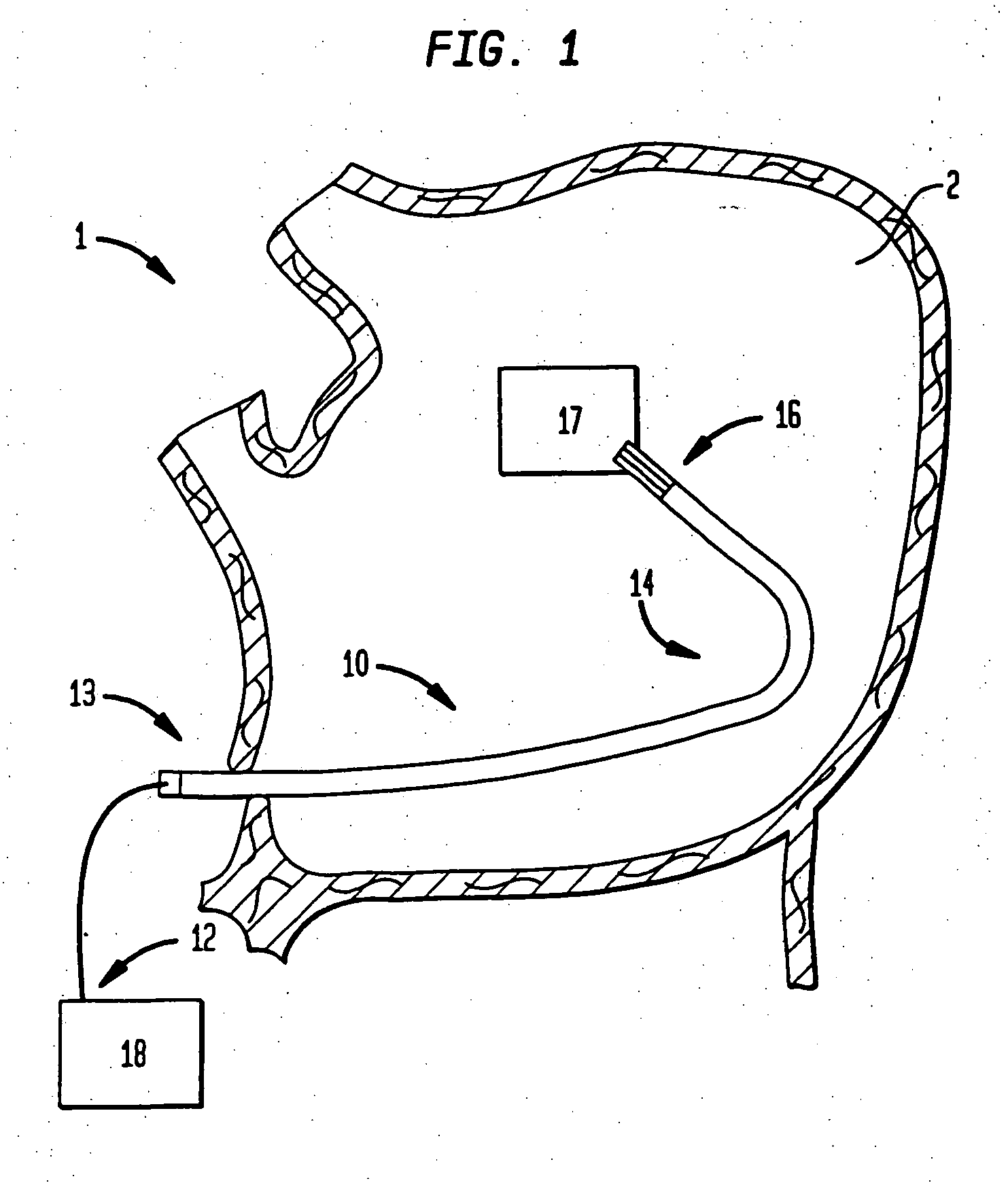
[0029] Referring to FIG. 1, the apparatus according to one embodiment of the invention is a catheter, generally identified as 10, having a generally depicted steering device 18 on its proximal end 12, an insertable catheter portion 13 which gets inserted into a subject, such as into a chamber 2 of the subject's heart 1, a steering portion 14 and a distal end 16.

[0030] The distal end 16 of the catheter 10 may house various tools and instruments 17 that facilitate the execution of different procedures, such as surgical ablation for example, at a target location in a subject. The distal end 16 is manipulated via the steering de...


PUM


Abstract

A steerable catheter has a steering portion incorporating a spear cut junction of catheter material, thereby providing for a gradual change in flexibility in the steering portion. A guide tube and spring may be located inside a pull wire lumen of the catheter, with the spring distal to the guide tube so that the spring is disposed at least partially within steering section. A steering mechanism moves the pull wire linearly in order to steer the catheter.

Description

CROSS REFERENCE TO RELATED APPLICATIONS [0001] This application is a continuation of application Ser. No. 11 / 141,426, filed May 31, 2005, the disclosure of which is hereby incorporated herein by reference.FIELD OF THE INVENTION [0002] The present invention generally relates to steerable catheters, and more particularly to the steering, responsiveness and kink resistance aspects of steerable catheters. BACKGROUND OF THE INVENTION [0003] Steerable, or deflectable, catheters are widely used in medical procedures to gain access to, and operate on, interior regions of the body. Such catheters have a distal end which can be remotely manipulated via a proximally located steering mechanism. In a typical medical procedure, the steering mechanism is located outside of the patient's body, and is manipulated in order to steer the distal end of the catheter to a desired location within the body. A steering catheter is disclosed, for example, in U.S. patent application Ser. No. 10 / 783,310, publis...

Claims


Application Information

Patent Timeline
Patent Type & Authority Applications(United States)
IPC IPC(8): A61M31/00
CPCA61B17/2202A61B17/22022A61B2017/003A61B2017/22024A61M2025/015A61M25/0054A61M25/0136A61M25/0141A61M25/0147A61B2017/22058
Inventor SAVAGE, JAMES D.MERINO, JAIME
Owner BOSTON SCI SCIMED INC
Why Eureka
Try Eureka