Embolic filter device and related systems and methods

a filter device and emboli technology, applied in the field of emboli filter devices, can solve the problems of not providing commercially viable filters that modify the surface of filters, the hemodynamics of blood flowing through filters may be substantially compromised, and the hemodynamics of the filter may be compromised

Inactive Publication Date: 2006-11-30
EMERGE MEDSYST
View PDF34 Cites 99 Cited by
  • Summary
  • Abstract
  • Description
  • Claims
  • Application Information

AI Technical Summary

Benefits of technology

[0025] One aspect of the present invention is an embolic filter system that includes a delivery member with an elongate body, and also a distal embolic filter assembly. The filter assembly includes a wall that is adapted to be delivered to a and span across a distal location within a vessel in a patient and that is substantially porous so as to filter emboli from antegrade blood flowing to and through the wall at the distal location. The wall is mounted on a super-elastic, nickel-titanium frame that is secured to the elongated bod...

Problems solved by technology

However, a commercially viable filter has not been provided that modifies the filter material surface to specifically enhance its biocompatibility or thrombus resistance.
A concern also remains that the hemodynamics of blood flowing through the filter may be substantially compromised to the extent causing hemolysis, a widely known precursor to a thrombotic cycle.
Such hemodynamic compromise may be caused, in one regard, by the size of flow pores themselves.
Notwithstanding this understanding from other fields, little has been done in the setting of filter membranes and other porous wall filters to engineer improvements against the potential thrombotic effects of lysis behind the filter membrane and surrounding the pores.
In another regard, notwithstanding whether thrombus forms on the device itself, the possible hemolysis caused by compromised fluid dynamics may still cascade to thrombotic events downstream of the filter.
However, no substantial effo...

Method used


Image

  • Embolic filter device and related systems and methods
  • Embolic filter device and related systems and methods
  • Embolic filter device and related systems and methods

Examples


Embodiment Construction

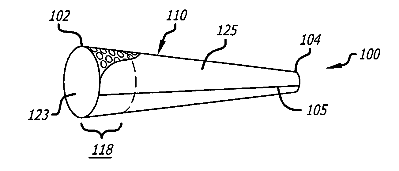
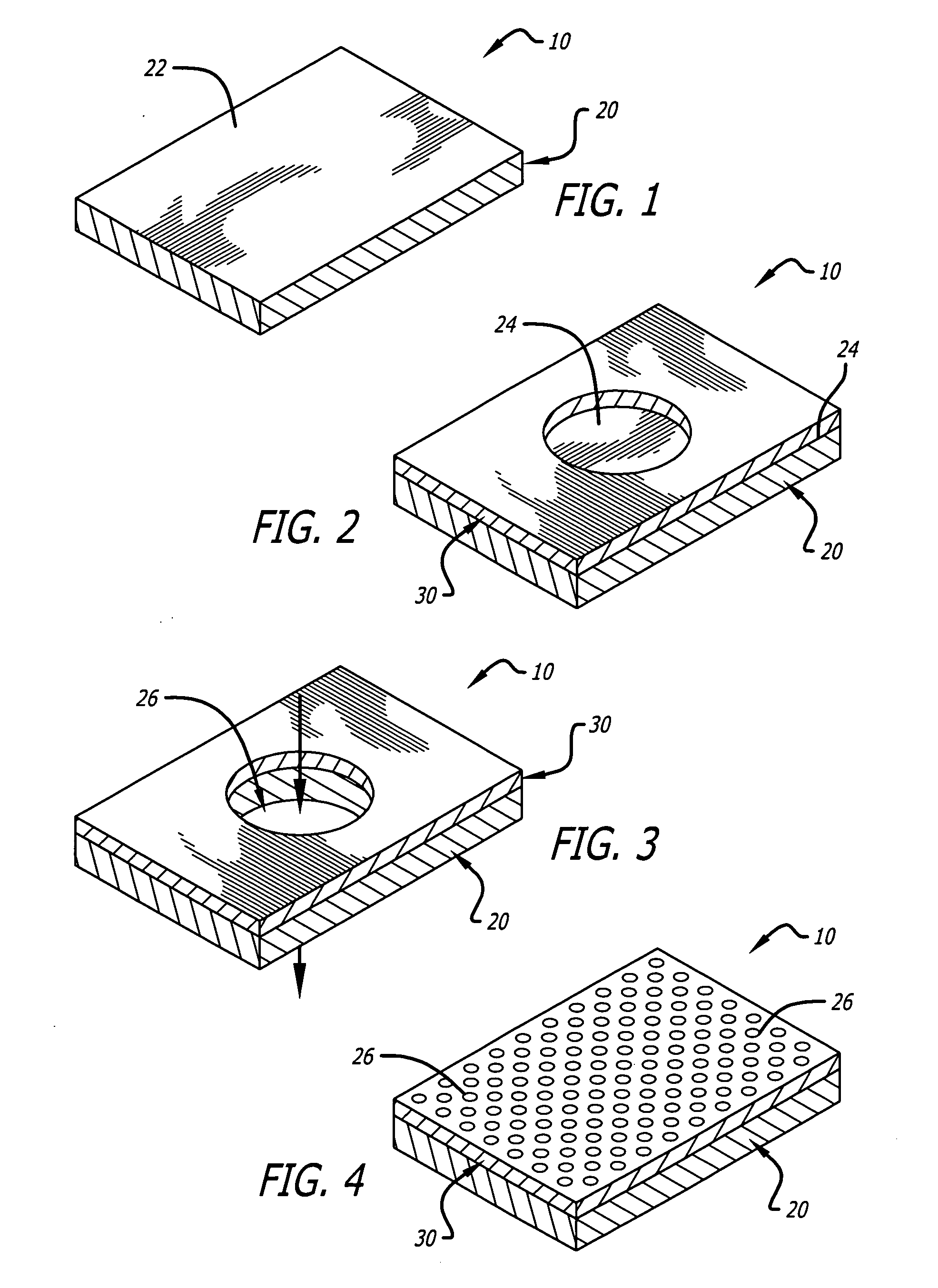
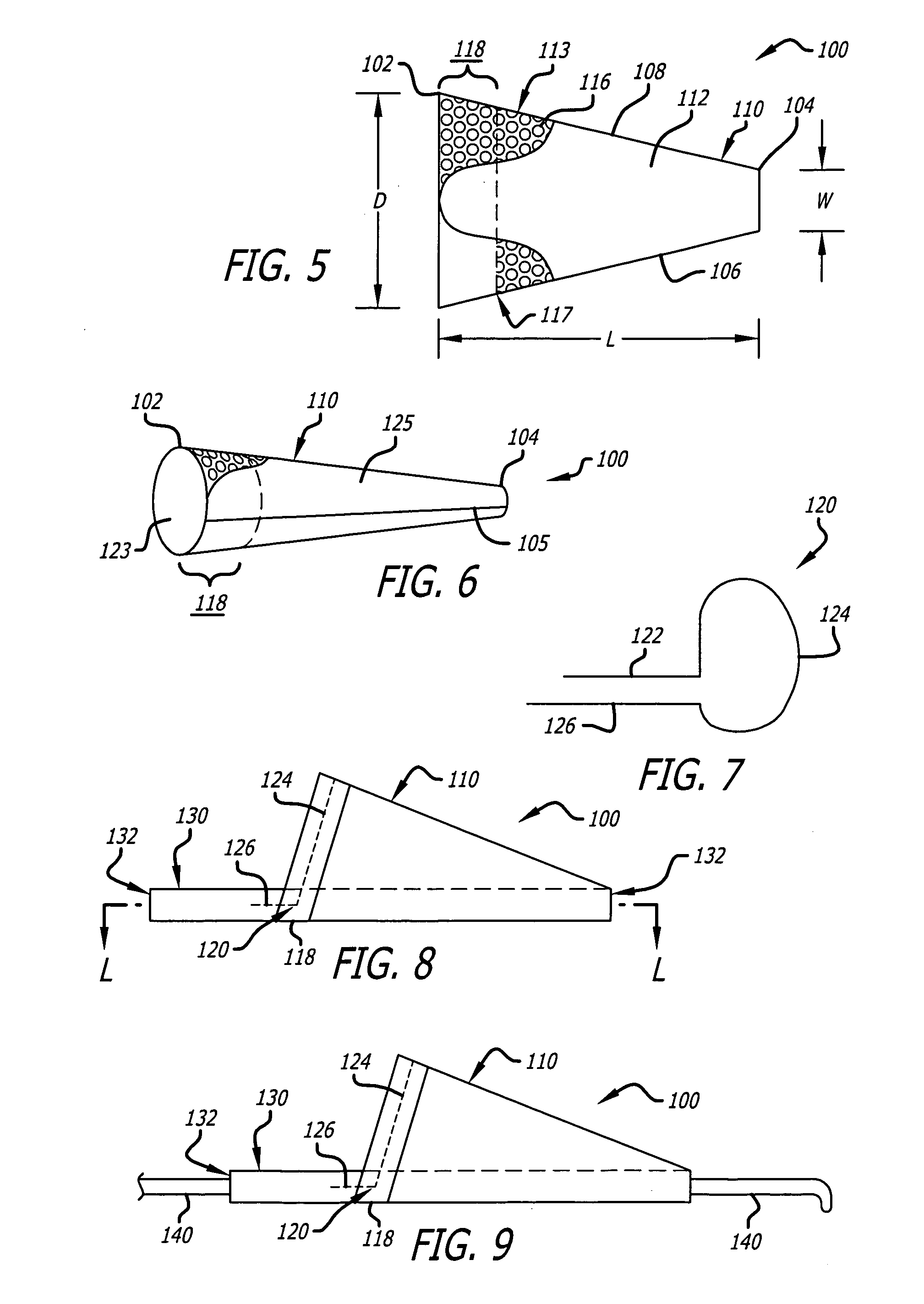
[0128]FIG. 1 to FIG. 18 show various modes of operation in preparing a distal embolic filter assembly, and various other embodiments and modes of use, according to various aspects of the present invention as follows.

[0129]FIG. 1 shows an illustrative portion of an initial form of a filter wall 10 that includes only a sheet of membrane material 20 that does not, at this stage, have an inherent porosity that is a desired porosity for embolic filtering. Nor does it provide all the surface features desired in an ultimate surface according to various of the present embodiments. However, it provides other desirable features as a wall material for use, and is used as a precursor material for preparation of the engineered material of desired porosity. Membrane 20 includes a top surface 22 that provides a platform upon which another second material will be deposited in order to achieve certain objectives of the embodiments described below.

[0130] For many materials and methods, patterned ab...


PUM


Abstract

An embolic filter system is provided that has a bioactive surface, such as locally on the surface itself or via elution into surrounding environs, and such as to debulk its filtered contents or prevent thrombosis or thromboemboli. An engineered wall provides for enhanced porosity for improved combination of blood flow through the filter and size of particulate that may be captured. Manufacturing methods are provided for improved filter assemblies, and a tether system is provided for improved in-situ deployment. A proximal filter assembly is used to debulk contents of a distal embolic filter assembly before it is removed from the patient.

Description

CROSS-REFERENCE TO RELATED APPLICATIONS [0001] This application claims priority from, and is a 35 U.S.C. § 111(a) continuation of, co-pending PCT international application serial number PCT / US2004 / 036415, filed on Oct. 28, 2004, incorporated herein by reference in its entirety, which designates the U.S., which claims priority from U.S. provisional application Ser. No. 60 / 515,282, filed on Oct. 28, 2003, wherein is herein incorporated in its entirety by reference.STATEMENT REGARDING FEDERALLY SPONSORED RESEARCH OR DEVELOPMENT [0002] Not Applicable REFERENCE TO A COMPUTER PROGRAM APPENDIX [0003] Not Applicable FIELD OF THE INVENTION [0004] The present invention is a system and method for filtering emboli from fluid flowing through a body lumen in a patient. More specifically, it is a distal embolic filter system and method providing an engineered porosity, and also providing reduction of emboli or biologic materials related to the filter. BACKGROUND [0005] Embolic filters have been wi...

Claims


Application Information

Patent Timeline
IPC IPC(8): A61M29/00A61F2/00A61F2/01A61M1/00
CPCA61F2/013A61F2250/0071A61M1/0056A61F2230/0067A61F2002/018A61F2230/0008A61M2202/0413A61F2/0105A61M1/79
Inventor PEACOCK, JAMES C. III
Owner EMERGE MEDSYST
Why Eureka
Try Eureka