Heating apparatus

a technology of heating apparatus and heating chamber, which is applied in the direction of metal working apparatus, manufacturing tools, and welding apparatus, etc., can solve the problems of inevitably suffering from a rise in temperature of the electronic component in the vicinity of the electronic component, and achieve the effect of preventing a rise in temperature and a rapid rise in temperatur

Inactive Publication Date: 2006-12-07
FUJITSU LTD
View PDF5 Cites 17 Cited by
  • Summary
  • Abstract
  • Description
  • Claims
  • Application Information

AI Technical Summary

Benefits of technology

[0017] The heating apparatus of the type allows the back surface of the printed wiring board to receive hot air from the auxiliary heating nozzle. An electronic component on the front surface of the printed wiring board is allowed to enjoy an efficient rise in the temperature. On the other hand, the auxiliary rectifier plate is located around the auxiliary heating nozzle. The auxiliary elastic insulating member is set continuous to the auxiliary rectifier plate. The auxiliary elastic insulating member serves to prevent the hot air from leaking out along the back surface of the printed wiring board into a space surrounding the auxiliary heating nozzle, for example. Other electronic component on the back surface of the printed wiring board is reliably prevented from rise in temperature.

Problems solved by technology

Other electronic component in the vicinity of the electronic component inevitably suffer from a rise in temperature during the heating of the electronic component in a conventional heating apparatus.

Method used


Image

  • Heating apparatus
  • Heating apparatus
  • Heating apparatus

Examples


first embodiment

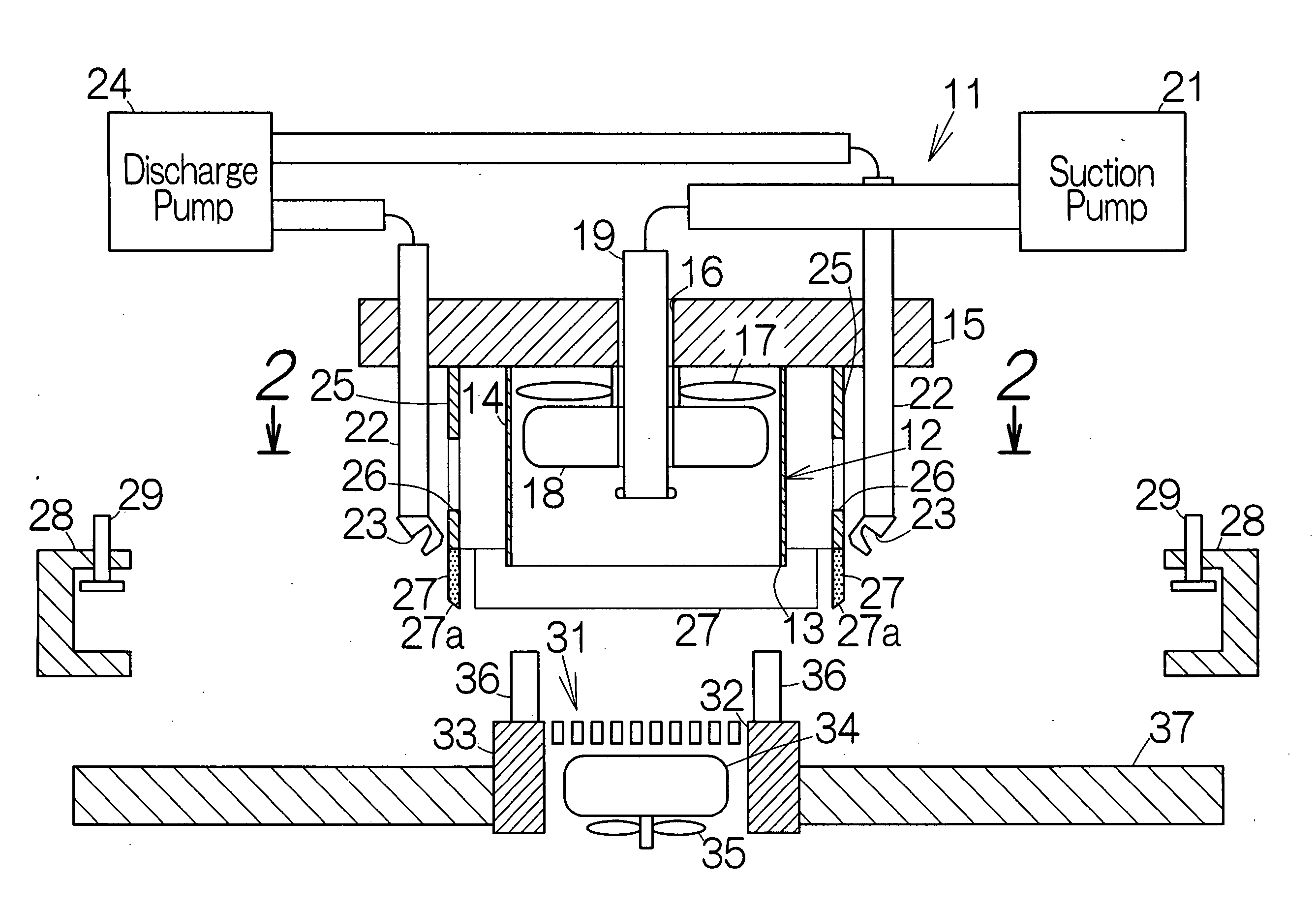
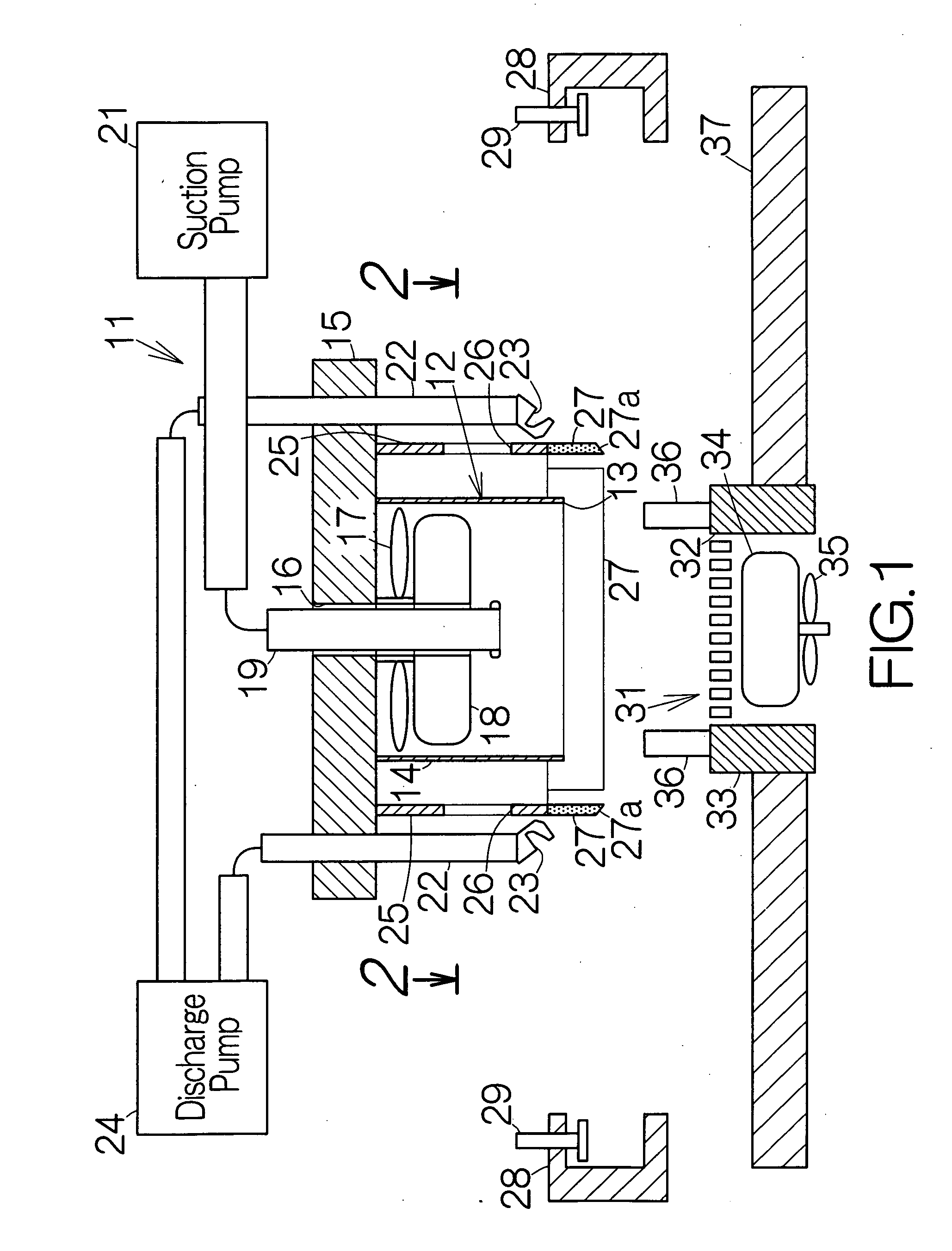
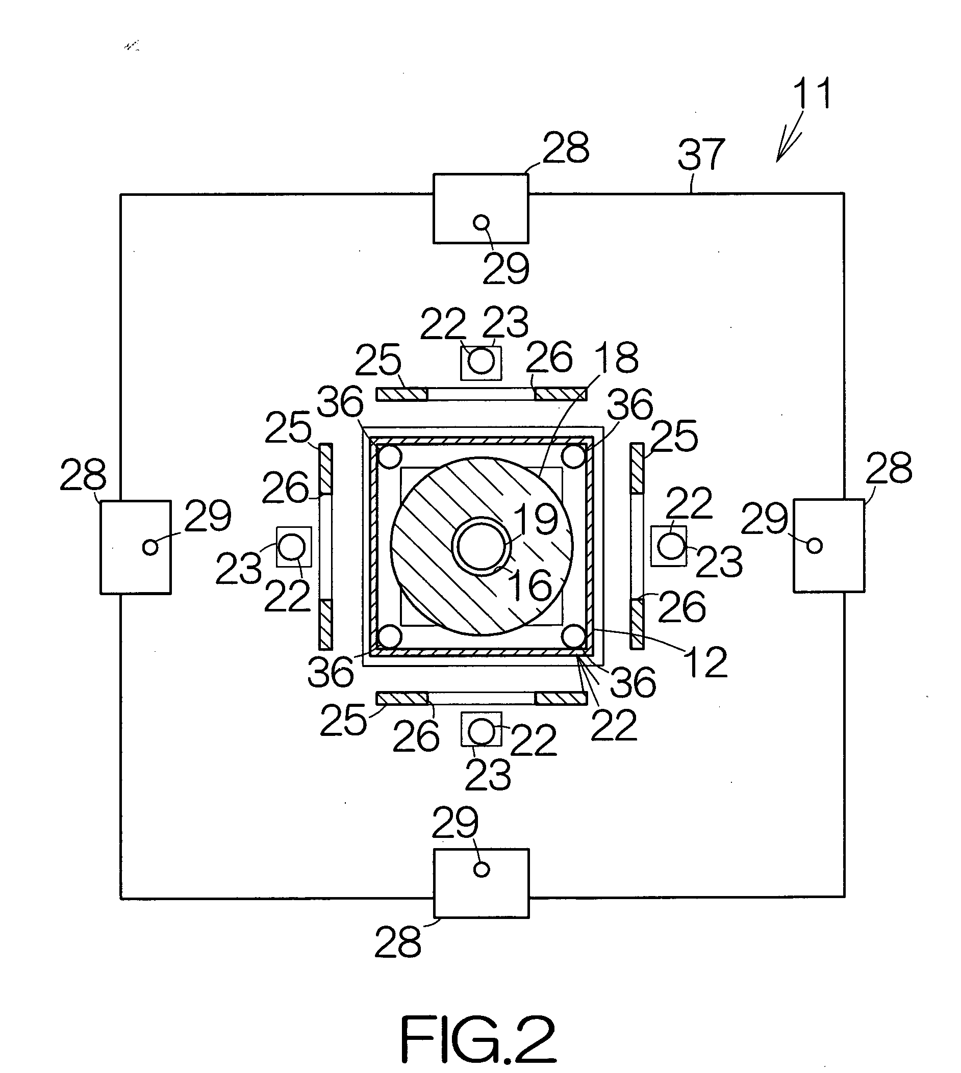
[0025]FIG. 1 schematically illustrates the structure of a heating apparatus 11 according to the present invention. The heating apparatus 11 includes a heating nozzle 12. The heating nozzle 12 includes a trunk or shell 14. The shell 14 defines a hexahedral inside space opened at a quadrilateral outlet 13 at the tip or lower end, for example. The shell 14 is fixed to a movable member 15. A support tube 16 is fixed to the movable member 15 inside the shell 14. The longitudinal axis of the support tube 16 is directed toward the outlet 13. The movable member 15 is allowed to move along the longitudinal axis of the support tube 16.

[0026] A blower fan 17 is set within the support tube 16 for relative rotation. The blower fan 17 generates airflow along the longitudinal axis of the support tube 16. The generated airflow is discharged from the outlet 13. A heater 18 is located in a space between the blower fan 17 and the outlet 13. The heater 18 may include a nickel / chrome / iron alloy wire as ...

second embodiment

[0051]FIG. 6 schematically illustrates a heating apparatus 11a according to the present invention. The heating apparatus 11a includes auxiliary air discharge nozzles 51 located around the auxiliary heating nozzle 31. The auxiliary air discharge nozzles 51 are fixed to the auxiliary heater 37, for example. An outlet 52 is defined at the tip end of the individual auxiliary air discharge nozzle 51. The outlet 52 is opened in the opposite direction from the auxiliary heating nozzle 31. The aforementioned discharge pump 24 may be connected to the auxiliary air discharge nozzles 51. The auxiliary air discharge nozzles 51 enable generation of airflow at positions distanced from the auxiliary heating nozzle 31.

[0052] The heating apparatus 11a further includes auxiliary rectifier plates 53 located around the auxiliary heating nozzle 31. The auxiliary rectifier plates 53 may be fixed to the auxiliary heater 37, for example. The individual rectifier plate 53 is located in a space between the a...


PUM

PropertyMeasurementUnit
heatproof temperatureaaaaaaaaaa
temperatureaaaaaaaaaa

Abstract

The heating apparatus allows an outlet of a heating nozzle to get opposed to an electronic component during detachment of the electronic component from a printed wiring board. Hot air blown out of the outlet of the heating nozzle is utilized to heat the electronic component. Electrically-conductive terminals thus melt between the electronic component and the printed wiring board. An air discharge nozzle is located in the vicinity of the heating nozzle. The air discharge nozzle serve to generate airflow at a location distanced from the heating nozzle. The airflow serves to suppress rise in the temperature in the vicinity of the electronic component. Other electronic component in the vicinity of the electronic component is reliably prevented from rise in temperature. The other electronic component is thus prevented from destruction.

Description

BACKGROUND OF THE INVENTION [0001] 1. Field of the Invention [0002] The present invention relates to a heating apparatus often utilized for attachment and detachment of an electronic component such as an IC (Integrated Circuit) chip to and from the surface of a printed wiring board. [0003] 2. Description of the Prior Art [0004] A heating apparatus is often utilized for detachment of a defective IC chip from a printed wiring board in an IC package as disclosed in Japanese Patent Application Publication 2004-006453, for example. The heating apparatus includes a heating nozzle. The outlet of the heating nozzle is opposed to an IC chip. The heating nozzle is designed to blow hot air from the outlet to the IC chip. The hot air allows electrically-conductive terminals or bumps to melt in a space between the IC chip and the printed wiring board. The IC chip is then detached from the printed wiring board. [0005] Other electronic components are usually mounted around the IC chip on the print...

Claims


Application Information

Patent Timeline
Patent Type & Authority Applications(United States)
IPC IPC(8): B23K31/02
CPCB23K1/0016H01L2924/014B23K1/018B23K3/04B23K3/08B23K2201/42H01L24/75H01L24/81H01L2224/16H01L2224/75H01L2224/75252H01L2224/75301H01L2224/75981H01L2224/8121H01L2224/81815H01L2924/01029H01L2924/01047H01L2924/01082H01L2924/14H05K3/3494H05K2203/0195H05K2203/081H05K2203/1572H01L2924/01006H01L2924/01033H01L2924/0105B23K1/012B23K2101/42H01L24/98H01L2224/7511H01L2224/75251H01L2224/7531H01L2924/00011H01L2924/00014H01L2224/0401
Inventor SAITO, OSAMUISHIKAWA, TETSUJITERAUCHI, CHIE
Owner FUJITSU LTD
Why Eureka
Try Eureka